MM1 modular 3D printer
General
| Technical features | Electronic board |
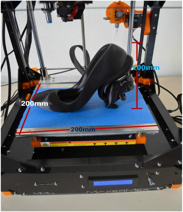
| Printing area 200mm x 200mm x 200 mm | RUMBA |
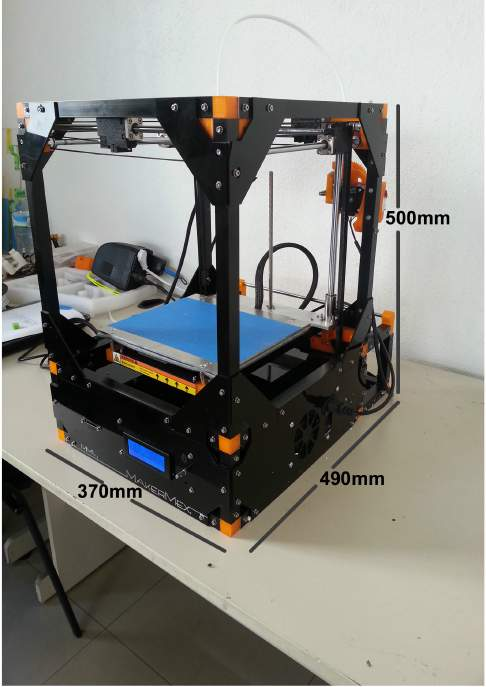
| Printer volume (aprox) 500mm x 370 mm x 490 mm | |
| Aprox weight: 11 kilogrames | |
| Needed voltage 12 volts |
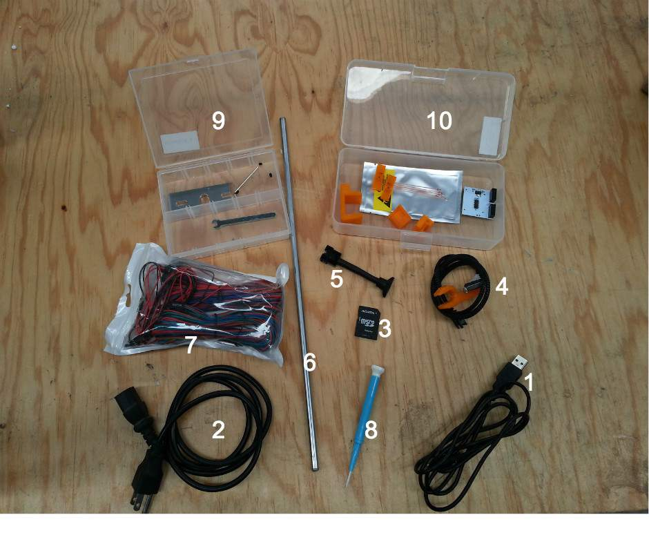
| What is included with my 3D printer? |
1.- USB Cable
2.- Power Cable
3.- SD Card
4.- Mechanical Z microswitch
5.- Dual extrusion tumbler
6.- Filament support
7.- Rep Rap cable kit
8.- Ceramic screwdriver
- 9.- Hexagon noozle kit
- Set screws
- Allen wrench
- Open end wrench
- Aluminum plate
- General spare parts
- SD drive
- Thermistors kit
- Shims
- K1, K2 parts
- 2 T tensors for the rubber belt
- V cables guide
Note
From the 3D printer with serial number 198 and above, dual extrusion tumbler is not necessary for the machine or any module, and is not included, this feature is now included in the controller firmware; if the serial number of your machine is lower than 198 and you want to update the firmware please contact our support team via the forum .
Note
As an aditional comment, all the digital manuals, tutorials and softwares as Cura, Blender and Pronterface are available for download in the MakerMex Wiki http://makermex.com/wiki/index.html. Also, as an owner of a MakerMex 3D printer you have two hours of technical support via video-call or in person (it must be schedulled with one day anticipation).
| PRINTING MODULES |
- Paste Module (prints chocolate, clay, ceramic, and a wide variety of pasty materials)
- CNC Modules (Rough soft materials)
- Drawing module (Creates technical drawings with high pecision)
- Flexible Módule (The Design of this module helps to print flexible materials as NinjaFlex, TPE and PLA Soft)
- Dul extrusion module (Combines two printing materials, it includes 2 hexagon noozles)
| ADVANTAGES |
- High quality 3D printing in a wide variety of materials
- Interchangeable header for each printing module.
- Open source plataform.
- Easy to replace pieces.
- Posibility to customization.
- Personalized support.
Unboxing
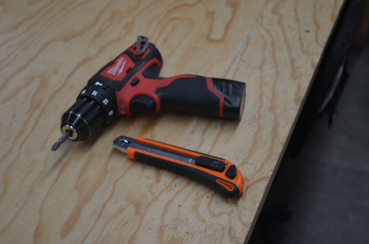
The first step to use your printer is the unboxing of it, to begin you will need two tools: a manual or electric screwdriver with philips shaft.
Note
In case you dont have a screwdriver, you can use a philips bit to remove the screws.
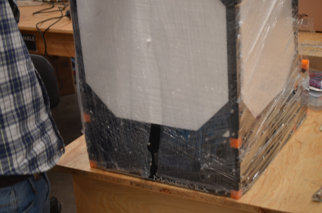
Step 1
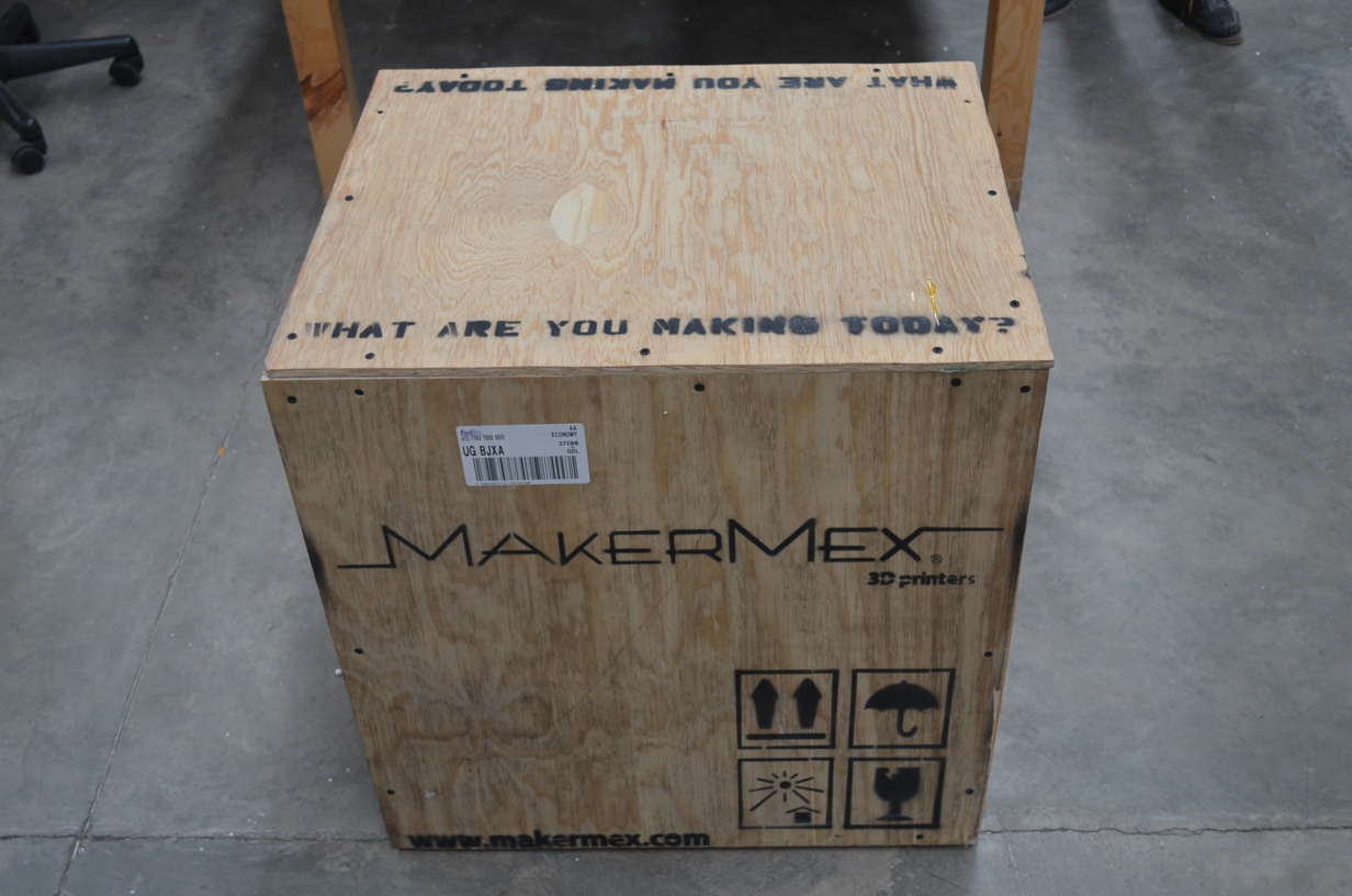
To begin with the unboxing of the pinter, first you have to make a quick inspection to ensure that the package is in good order, if the wooden box is damged please report the damage to the address listed at the end of this manual
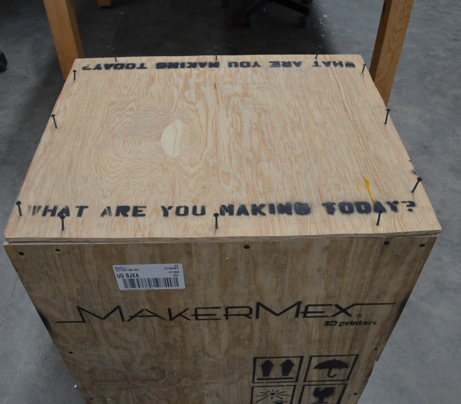
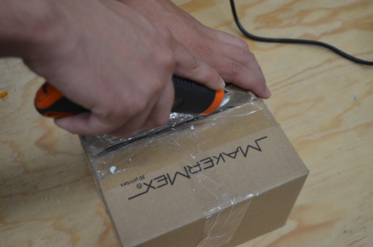
Step 2
Next, identify the top part of the packge and remove te screws one by one with a manual or electric screwdriver.
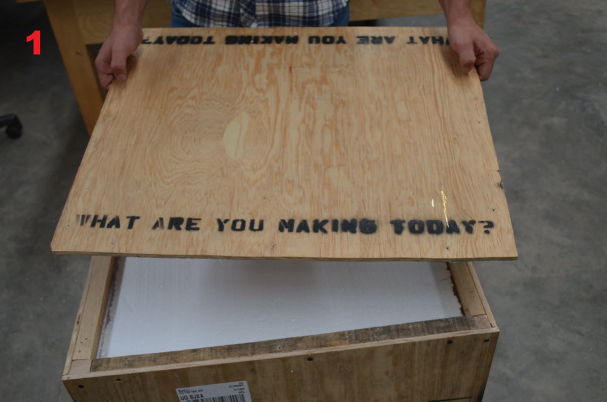
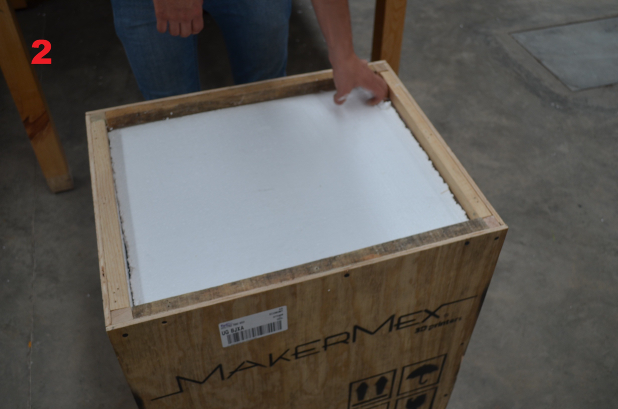
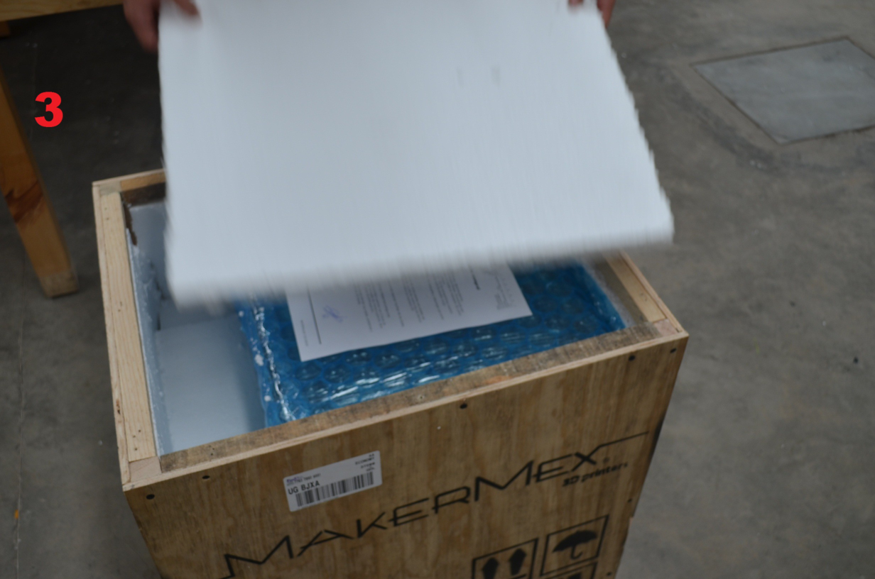
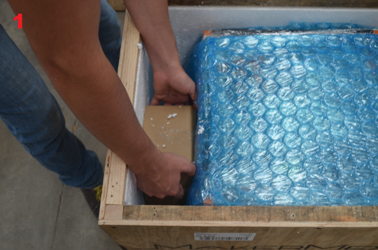
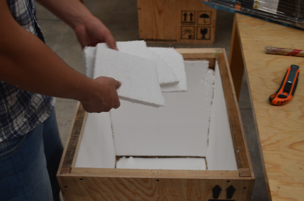
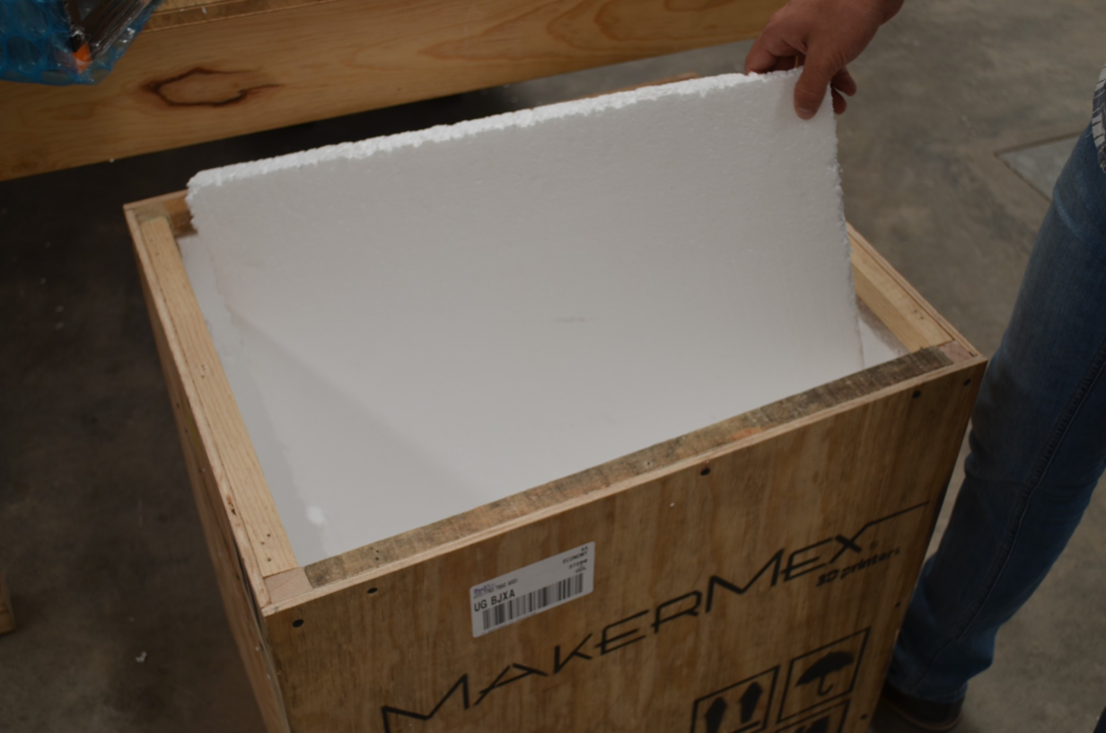
Step 3
In this step you have to identify the EPS foam supports at the bottom of the printer.
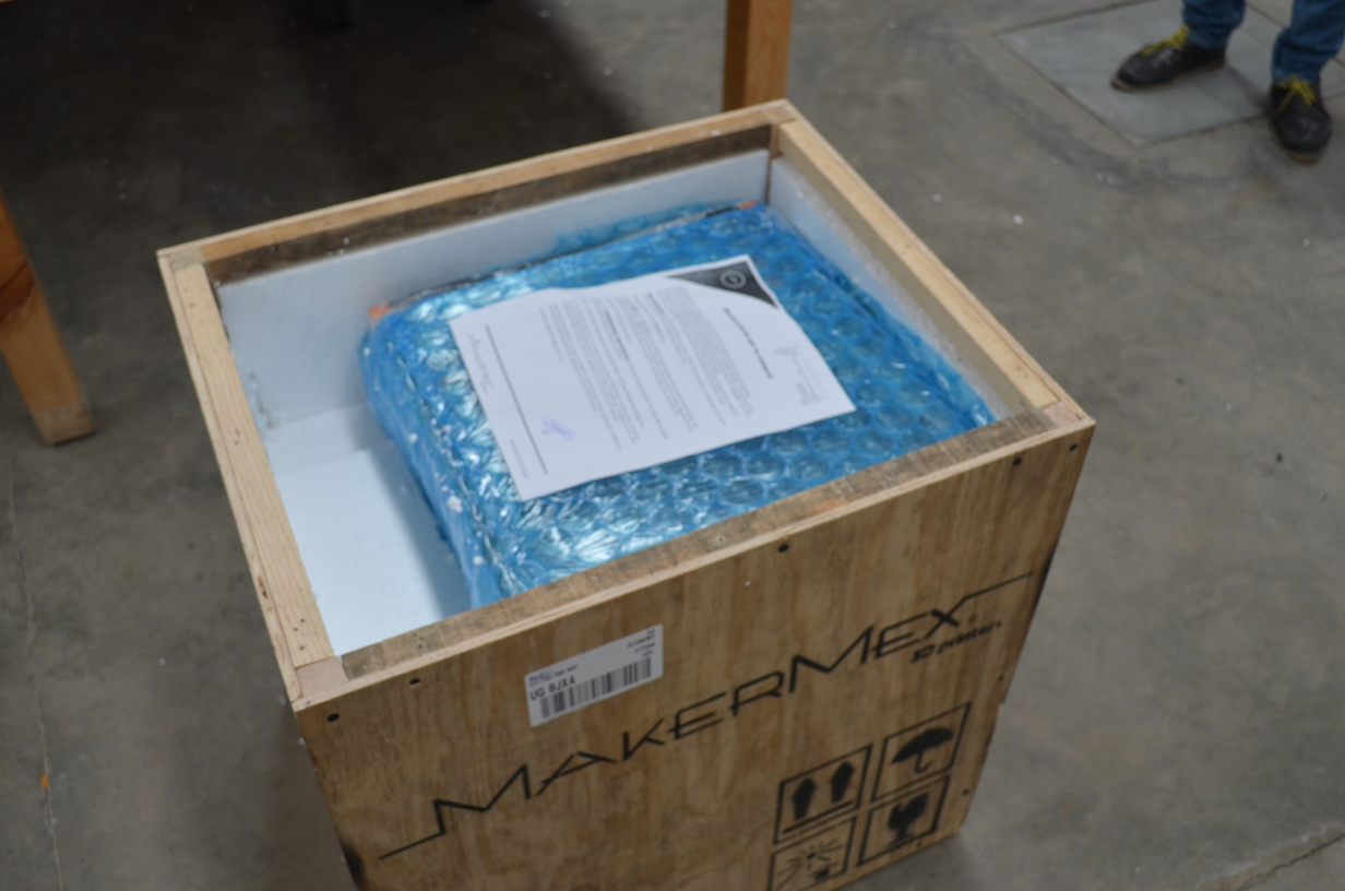
Once you have removed EPS Foam, lets gently take the printer components out of the box.
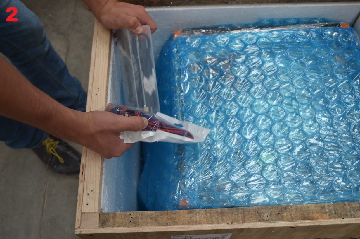
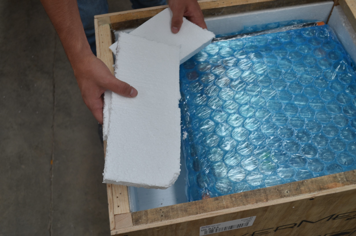
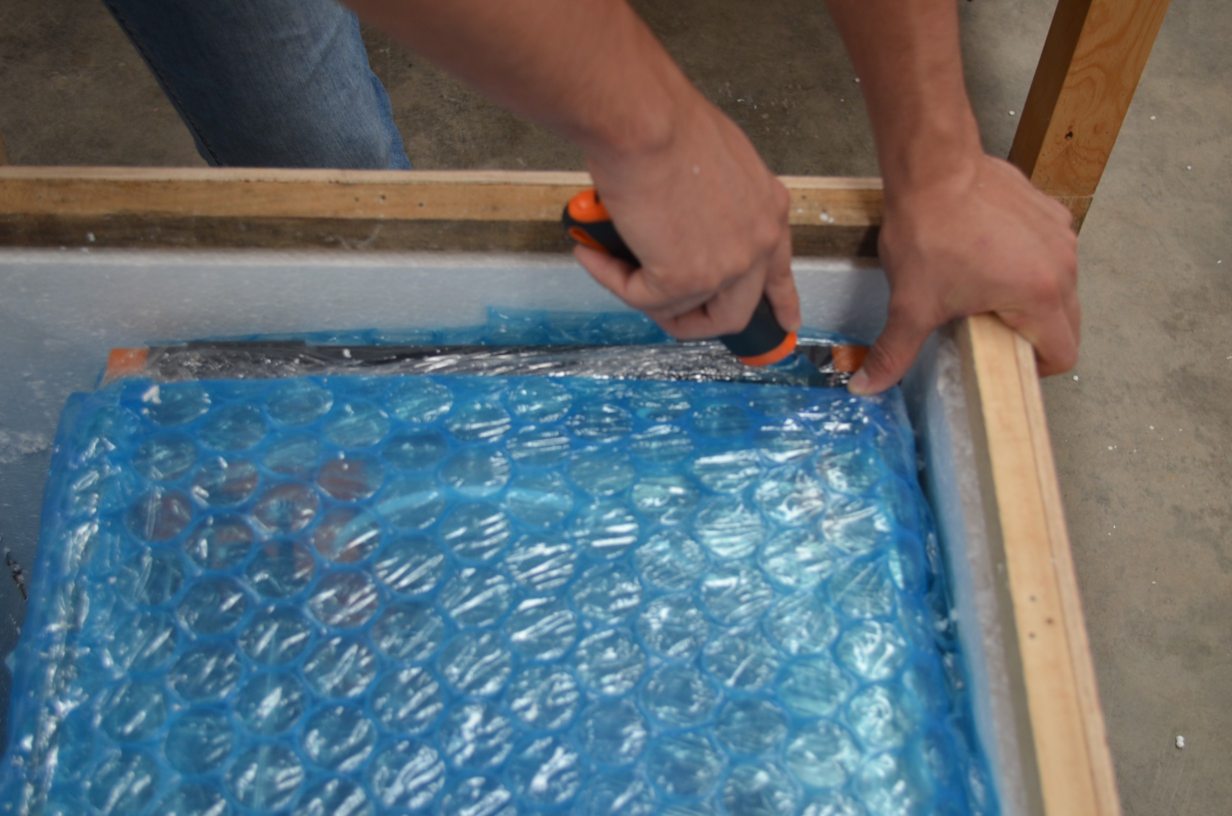
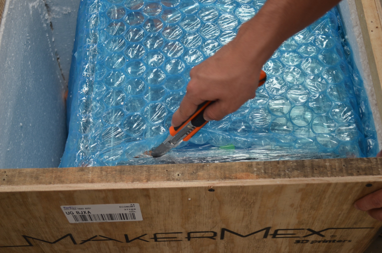
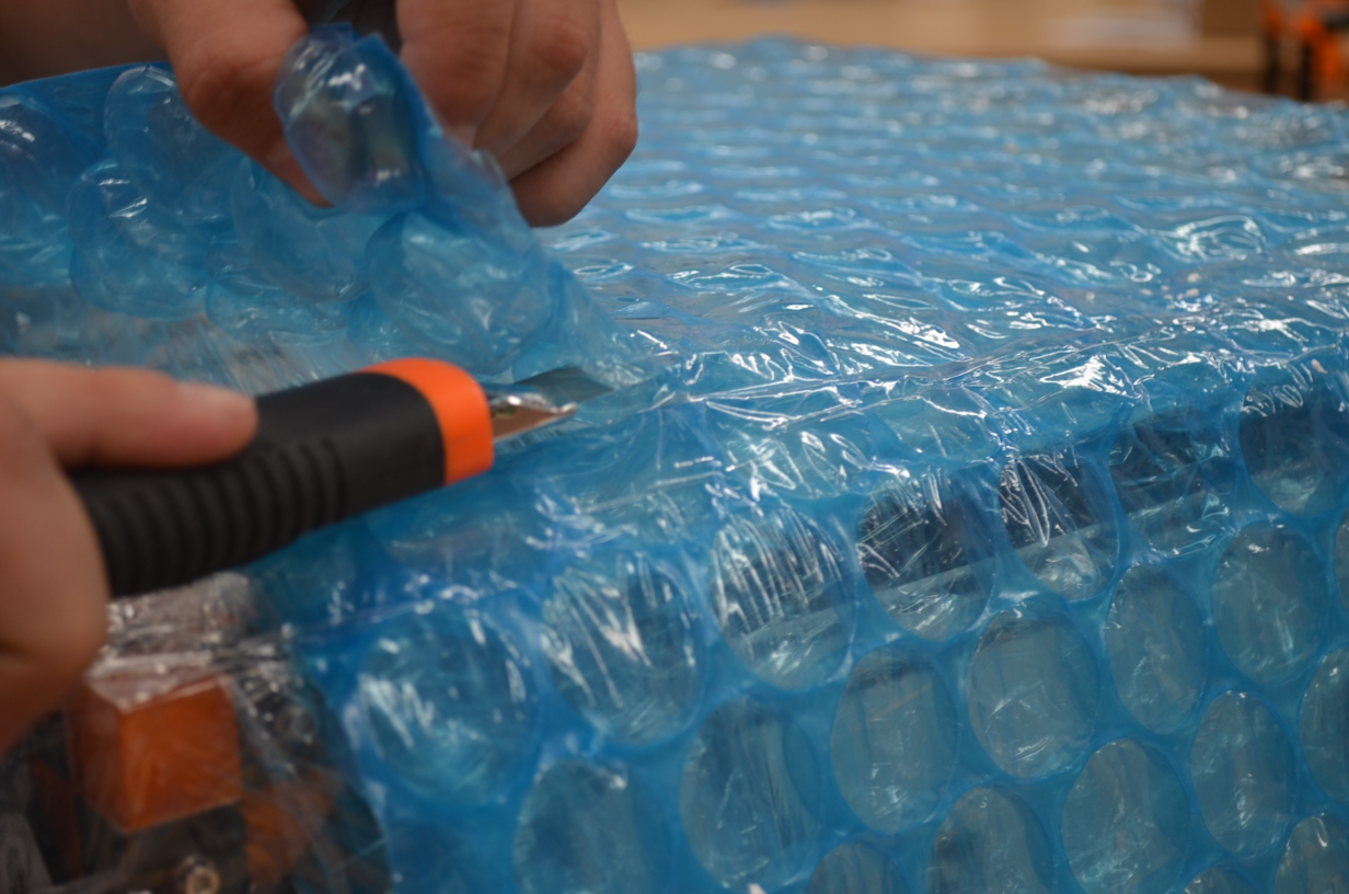
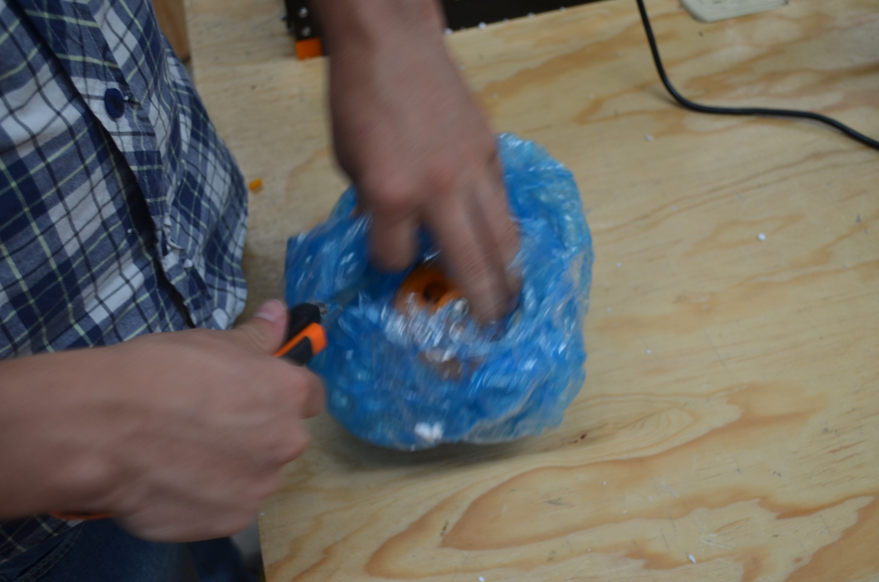
Step 4
In ths step, we will cut the bubble wrap, you must be careful cutting the bubble wrap in order to not to cut any of the wires of the printer. once you have cutted the bubble as shown in the images, you have to do two cuts as shown, this will make the next step easier for us.
Note
Be sure to have the printer in an an stable table to avoid any unwanted movement or vibration.
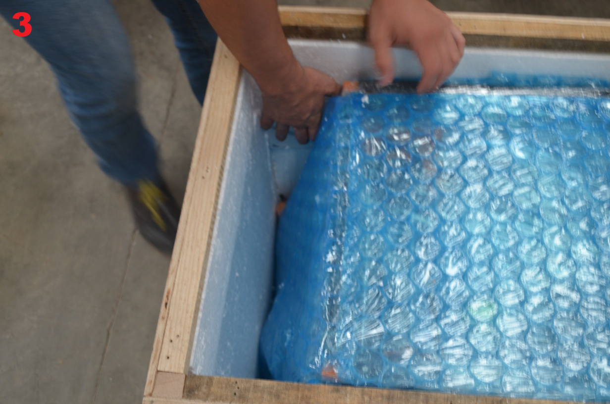
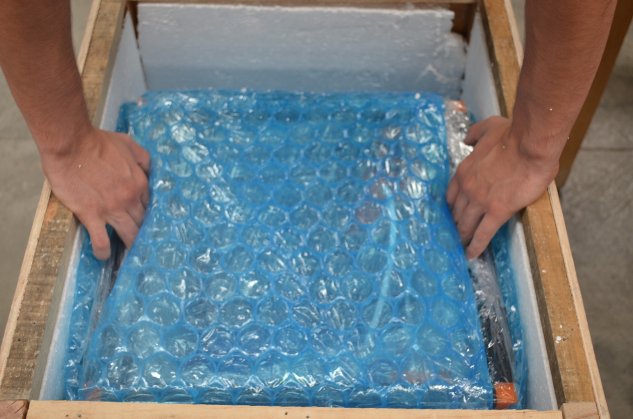
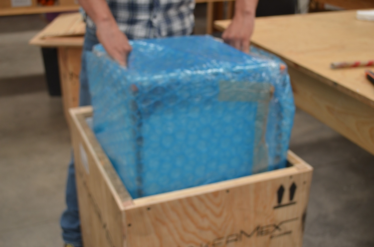
Step 5
After succesufully have cutted the buuble wrap, carefully hold the aluminum profiles on top (always face the printer in front of you) to get the printer out of the box, as shown in the images.
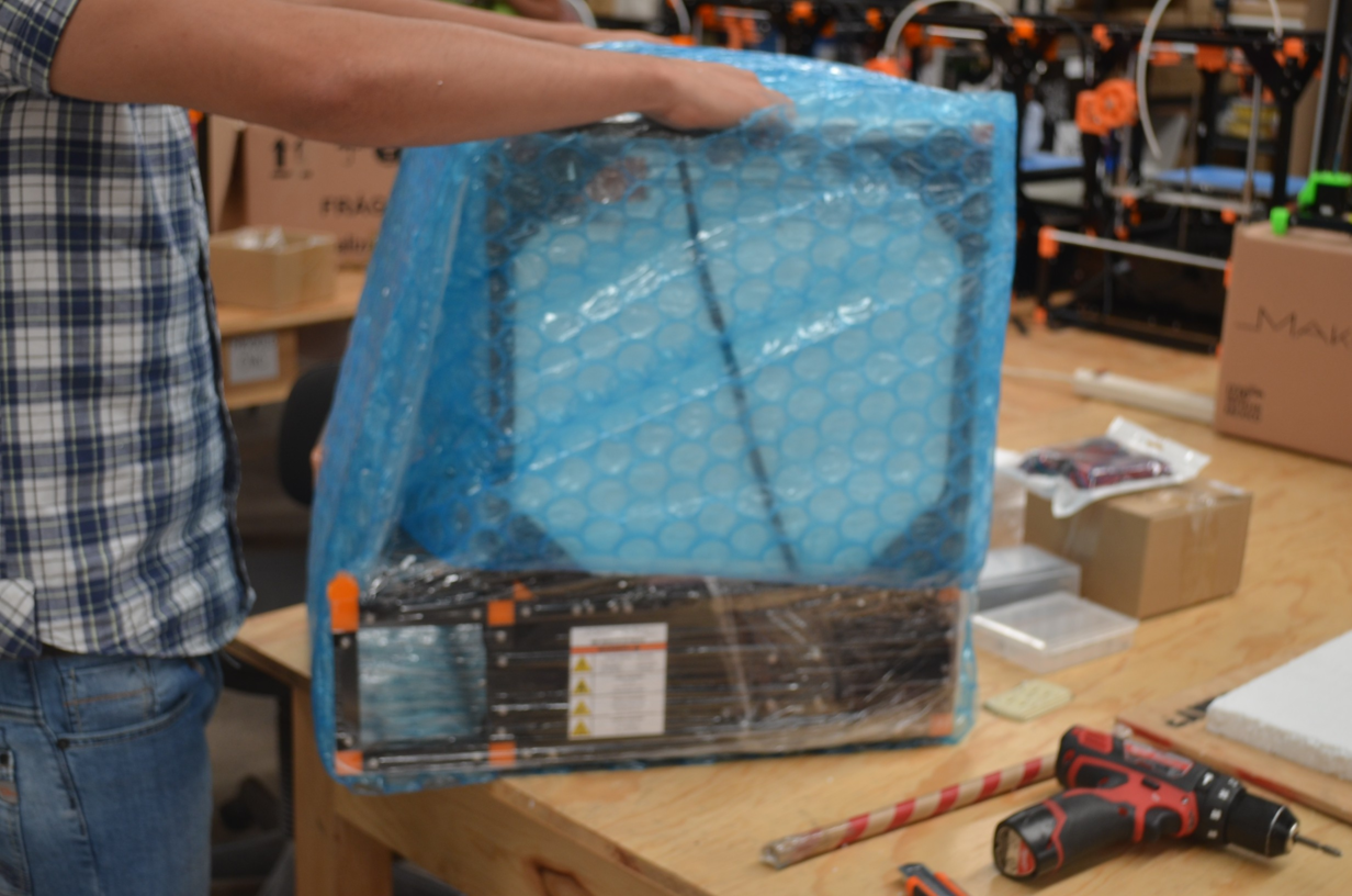
Note
As as suggestion, put back all the accesories in the box to avoid disorder.
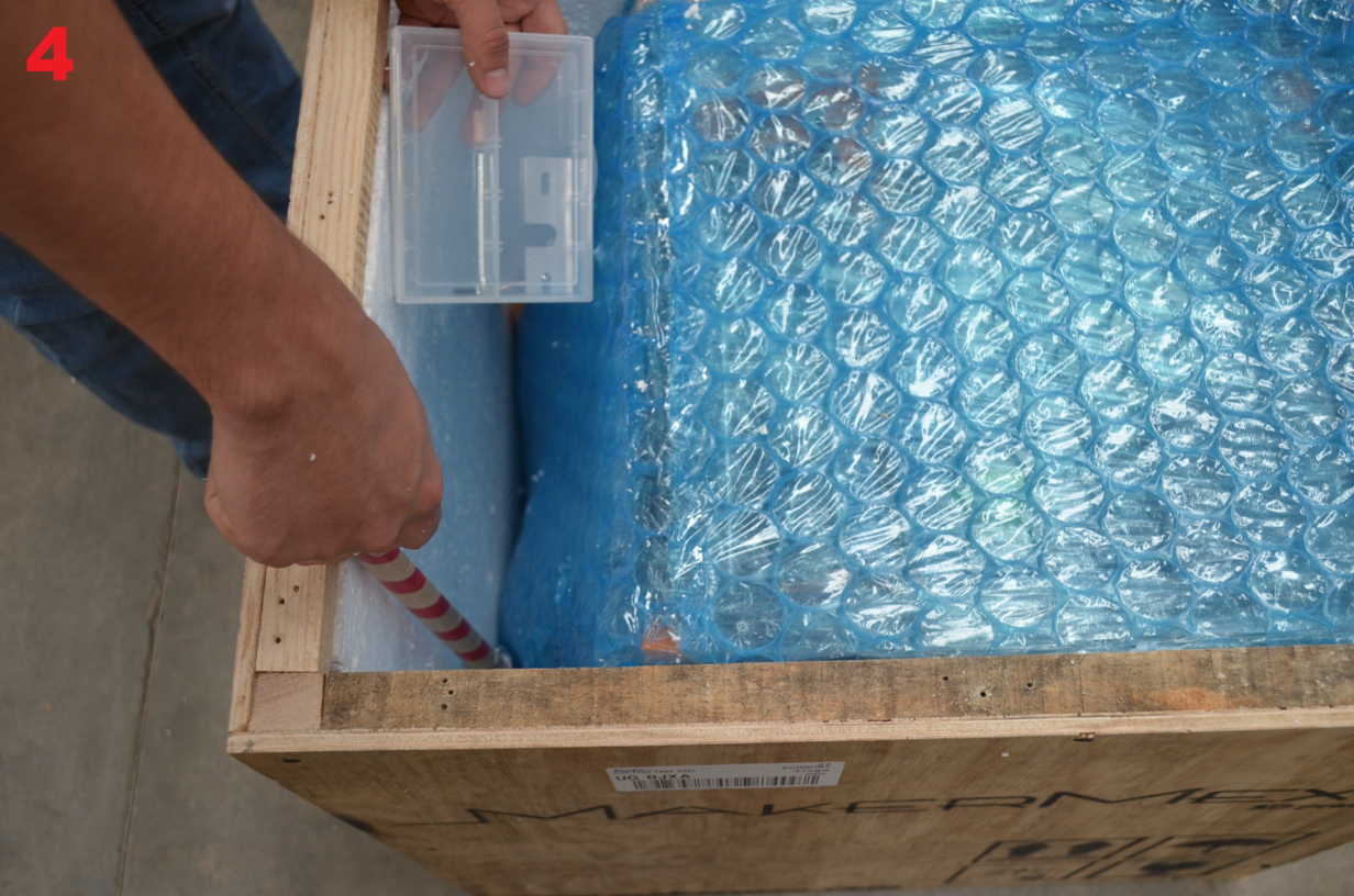
Step 6
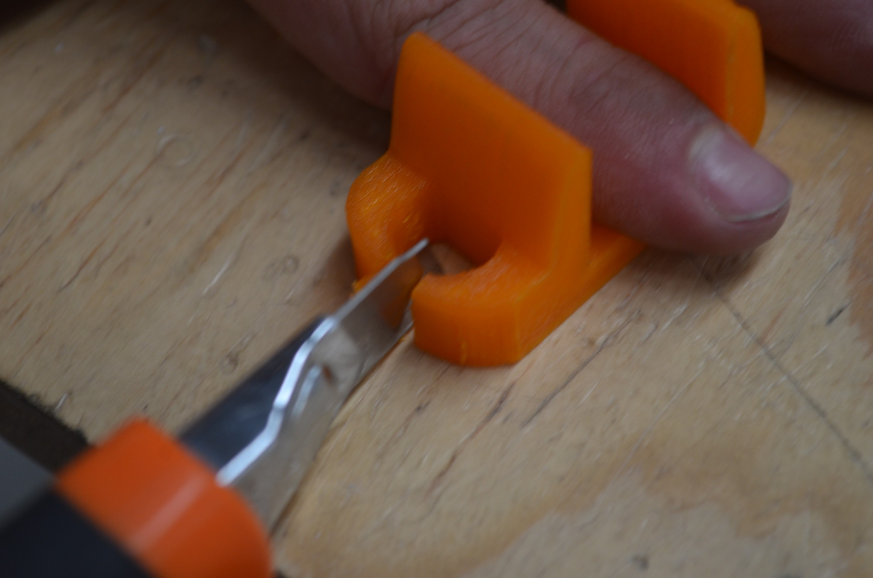
Next, we have to remove the excedent of bubble wrap using an utility knife, you can use the images below as a reference, also remove the EPS foam with the utility knife.
Step 7
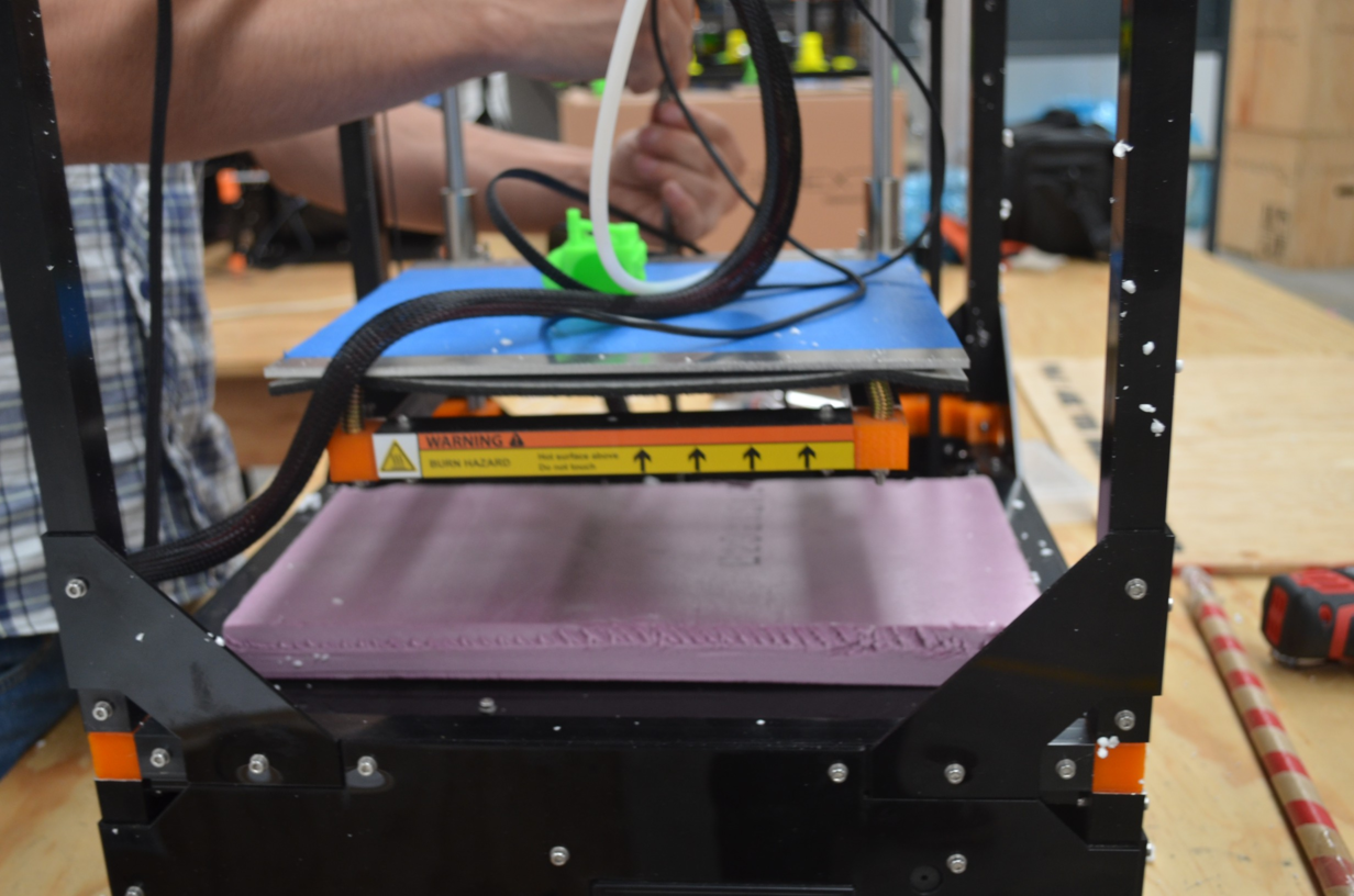
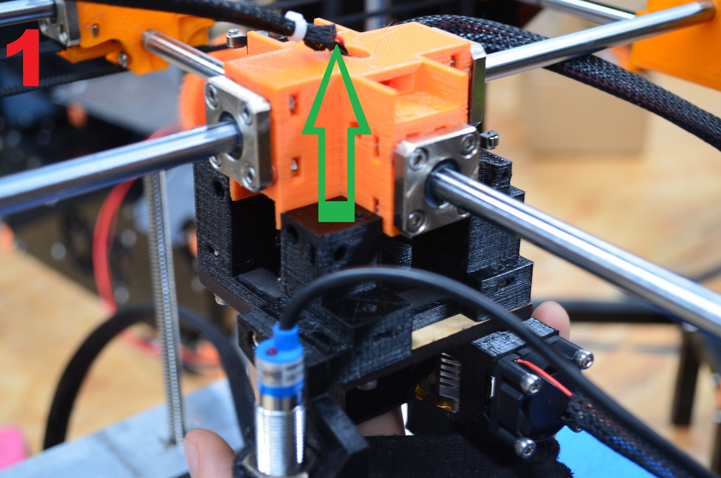
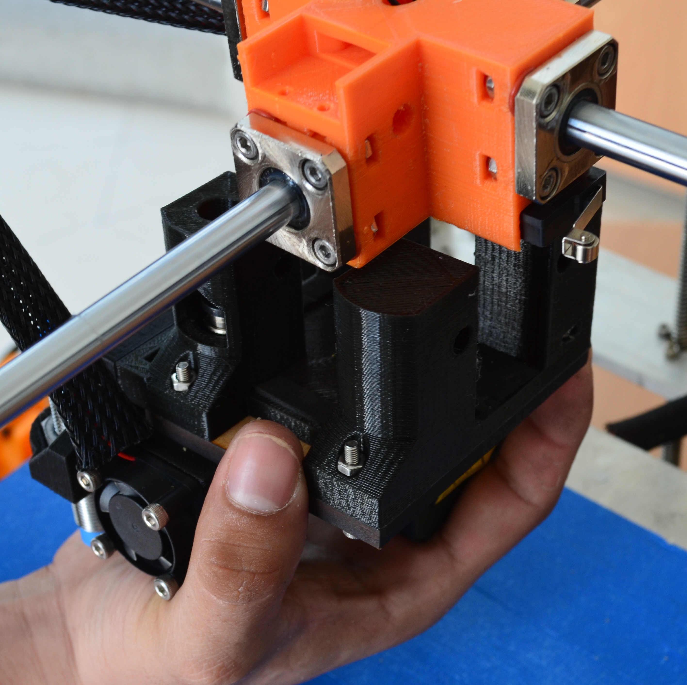
In this step you have to identify the plastic belts that holds parts of the printer, now, using the utility knife we will remove the belts that holds the central cross. Also you must cut the belt of the threaded rod, be very carefull to make sure you dont cut any of the the wires.
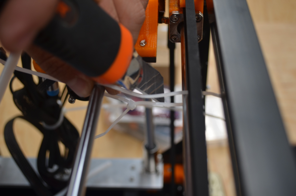
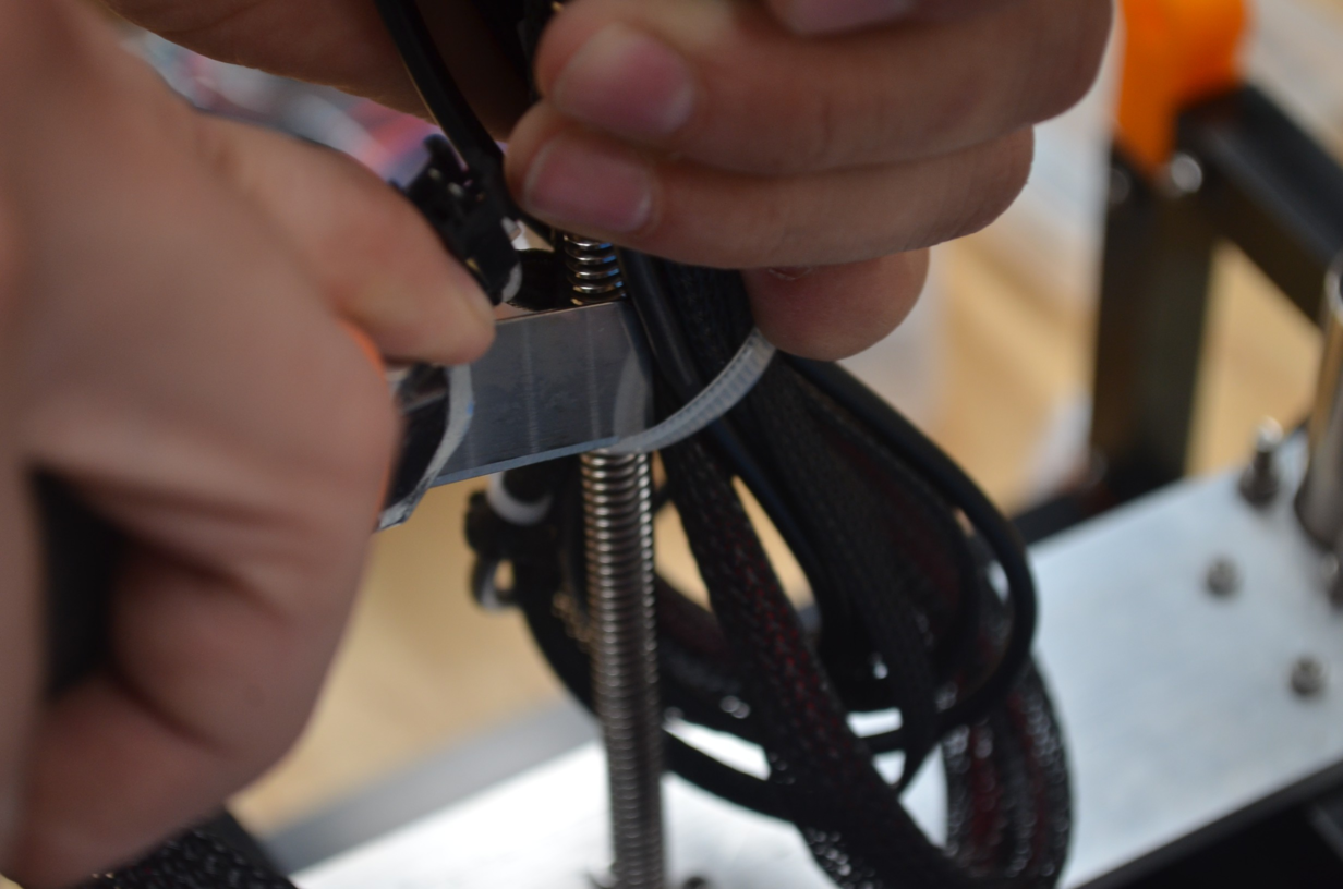
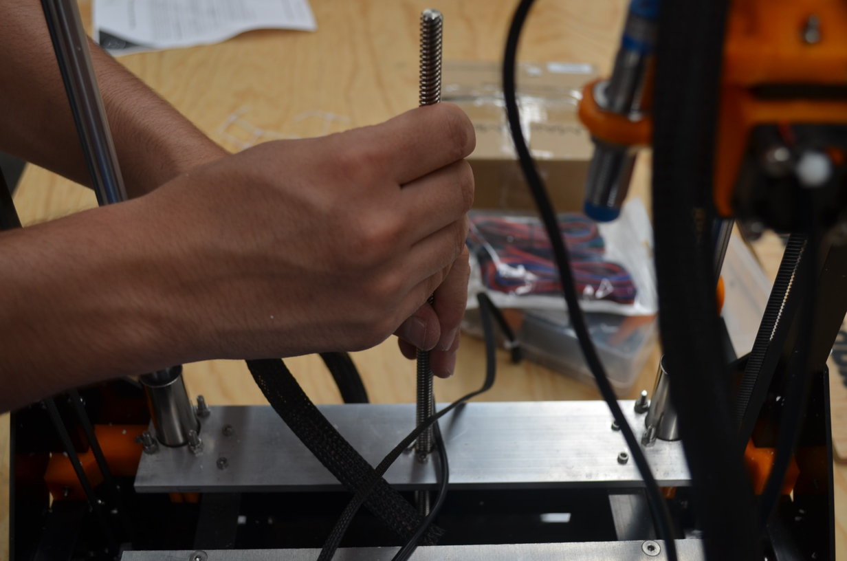
Once the axis is released, we turn some times so it gets up, then remove the pink support colocated in the bottom part of the machine.
Step 8
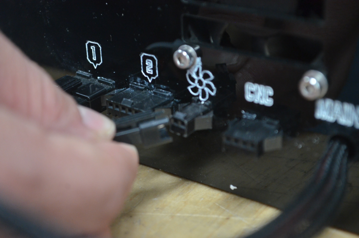
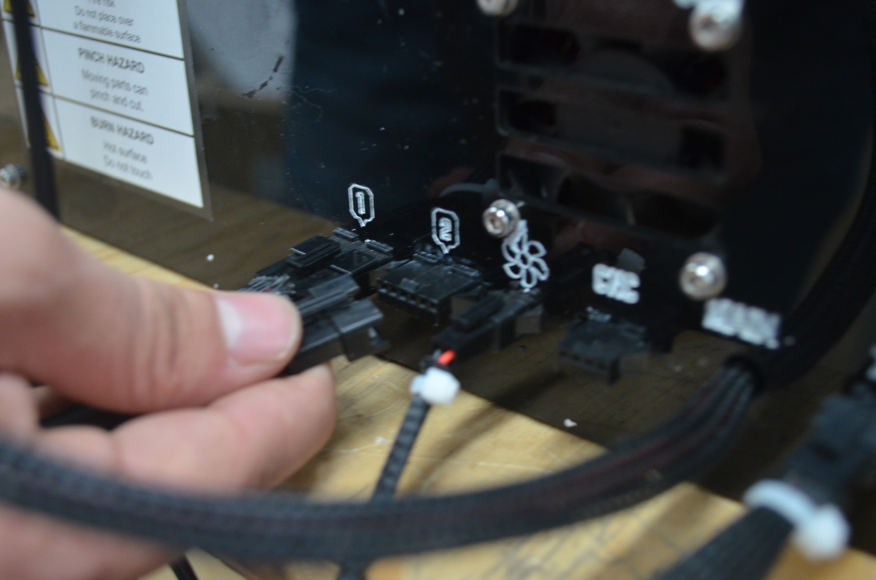
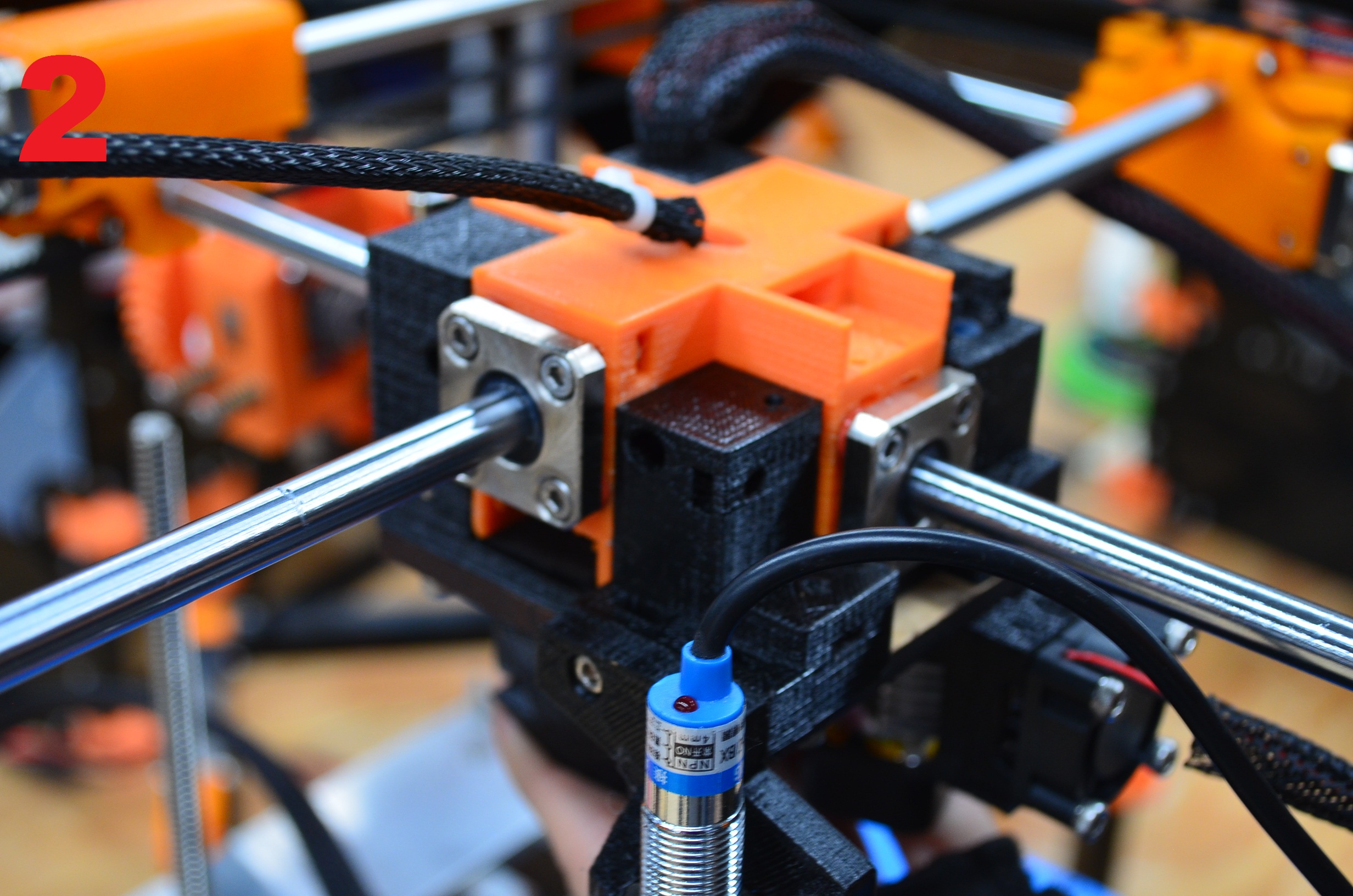
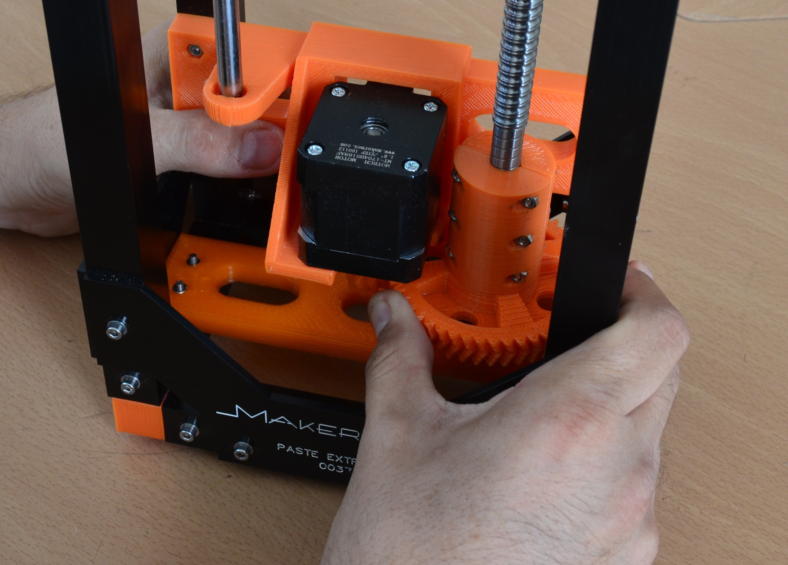
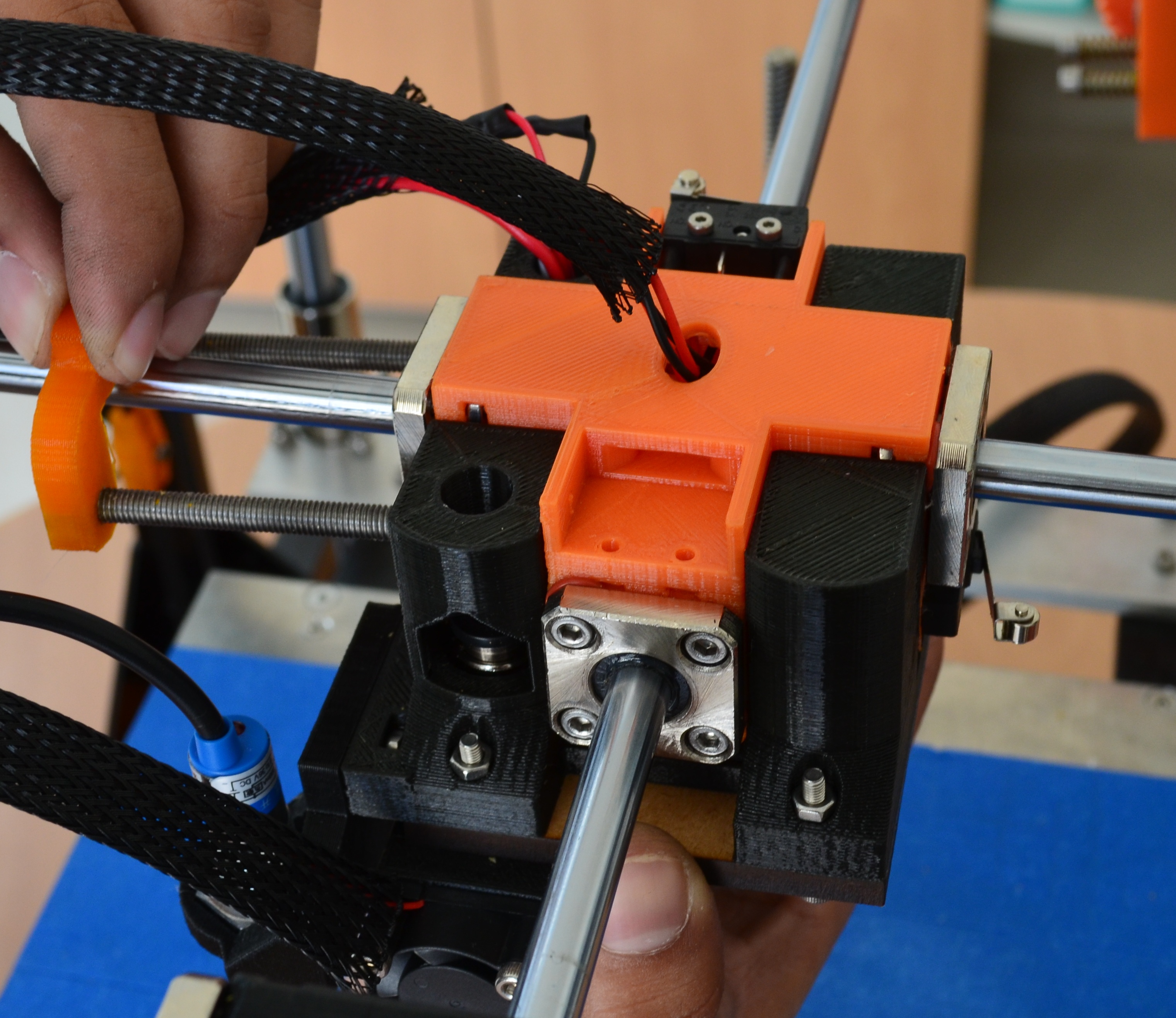
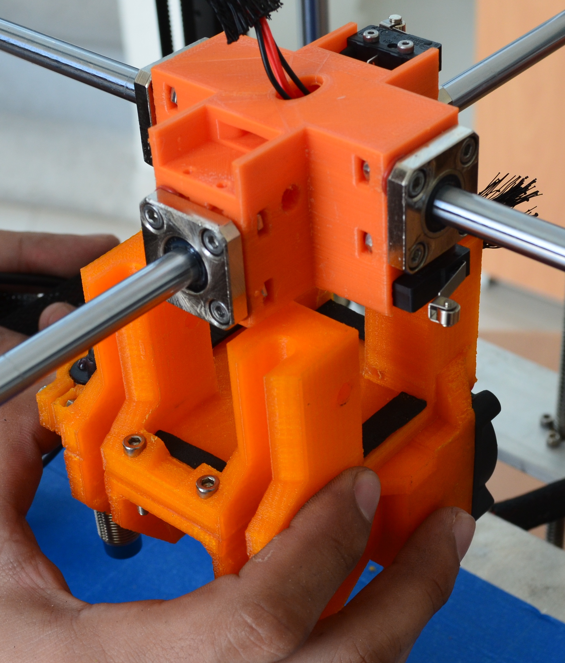
Now we put the cross in the center part of our printer, next we will connect the wires that belongs to the lateral connectors of the printer, lets see the images below.
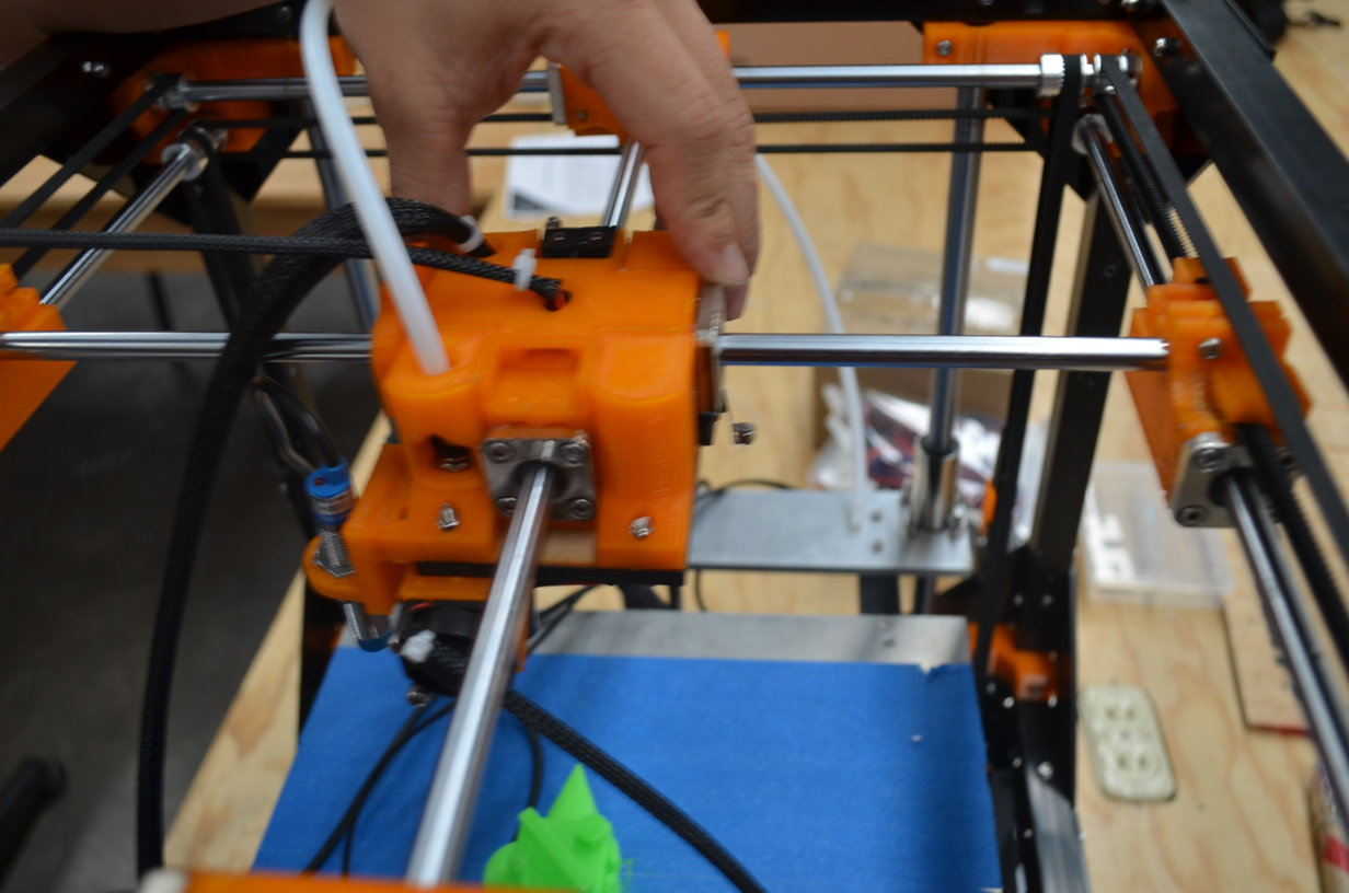
Now,we pass the wires of the module, over the top left profile (looking the front of the printer).
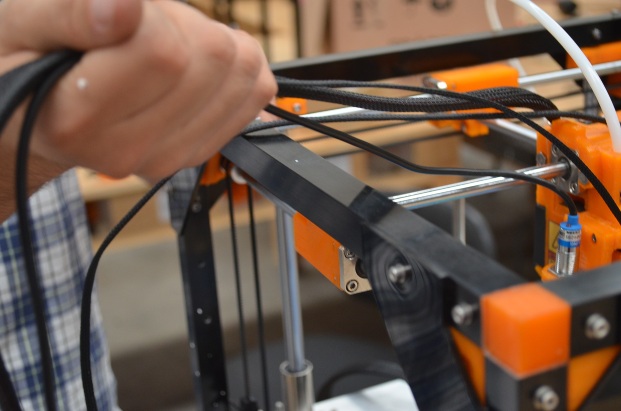
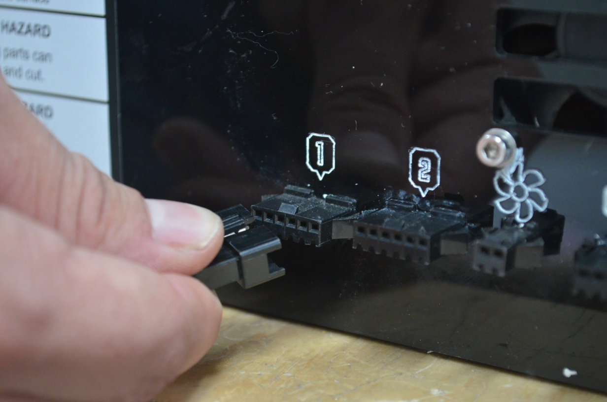
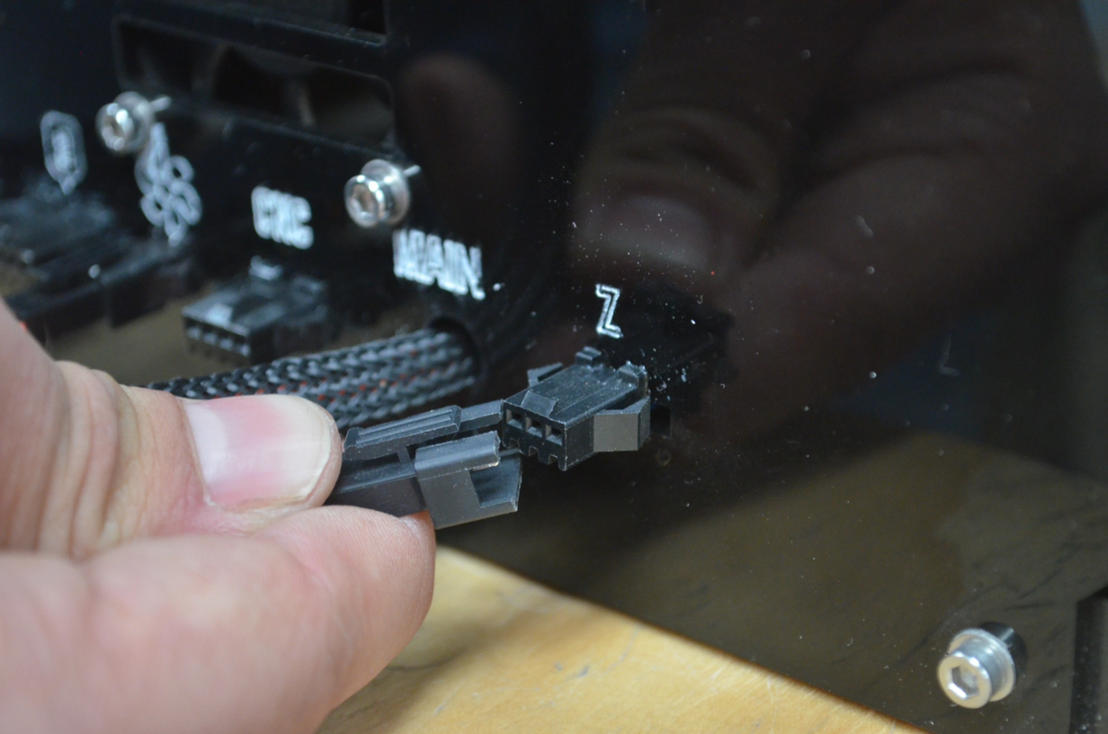
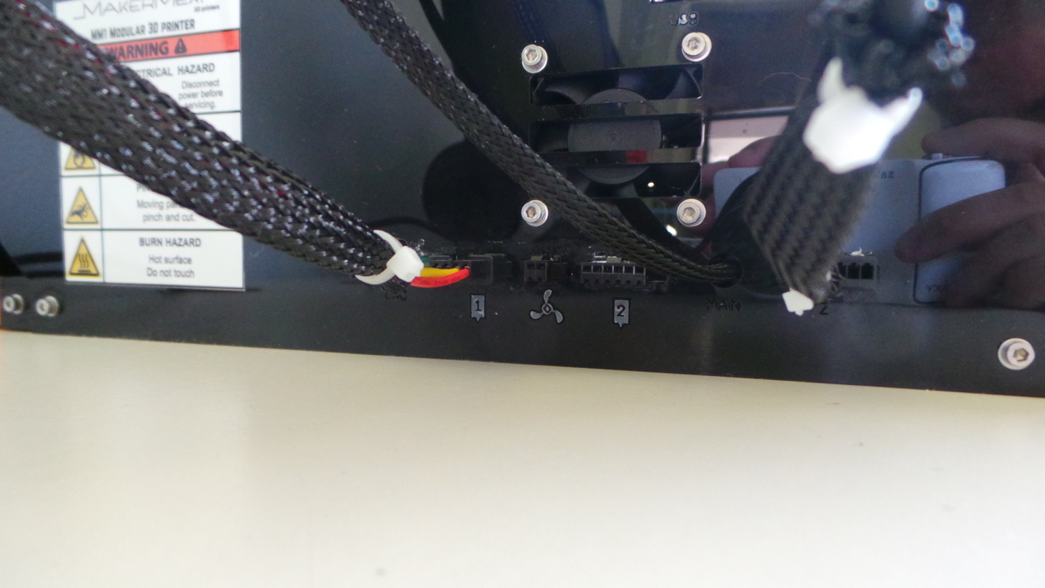
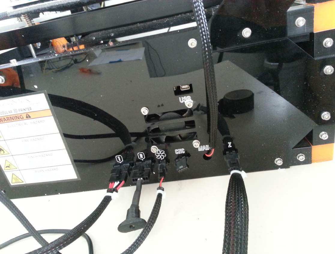
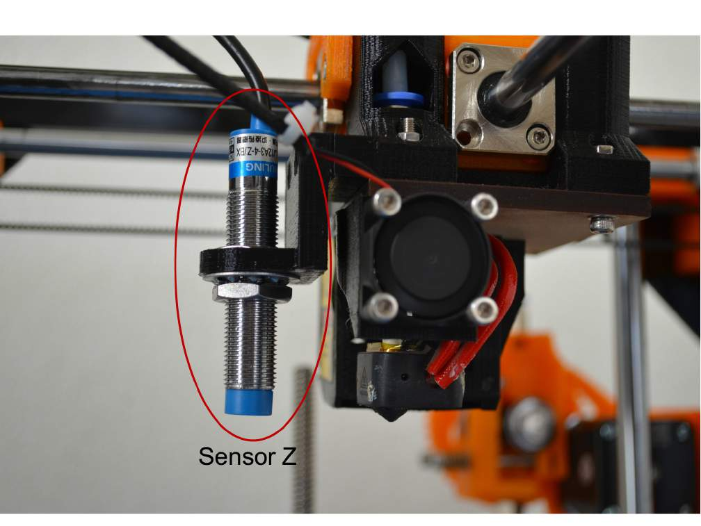
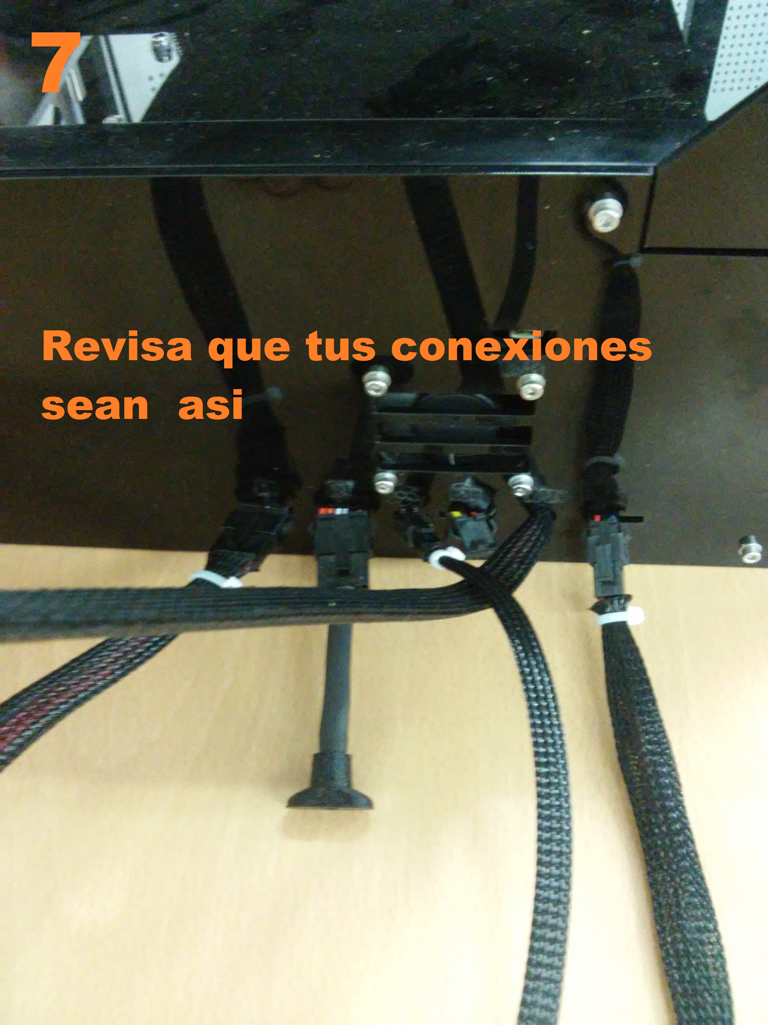
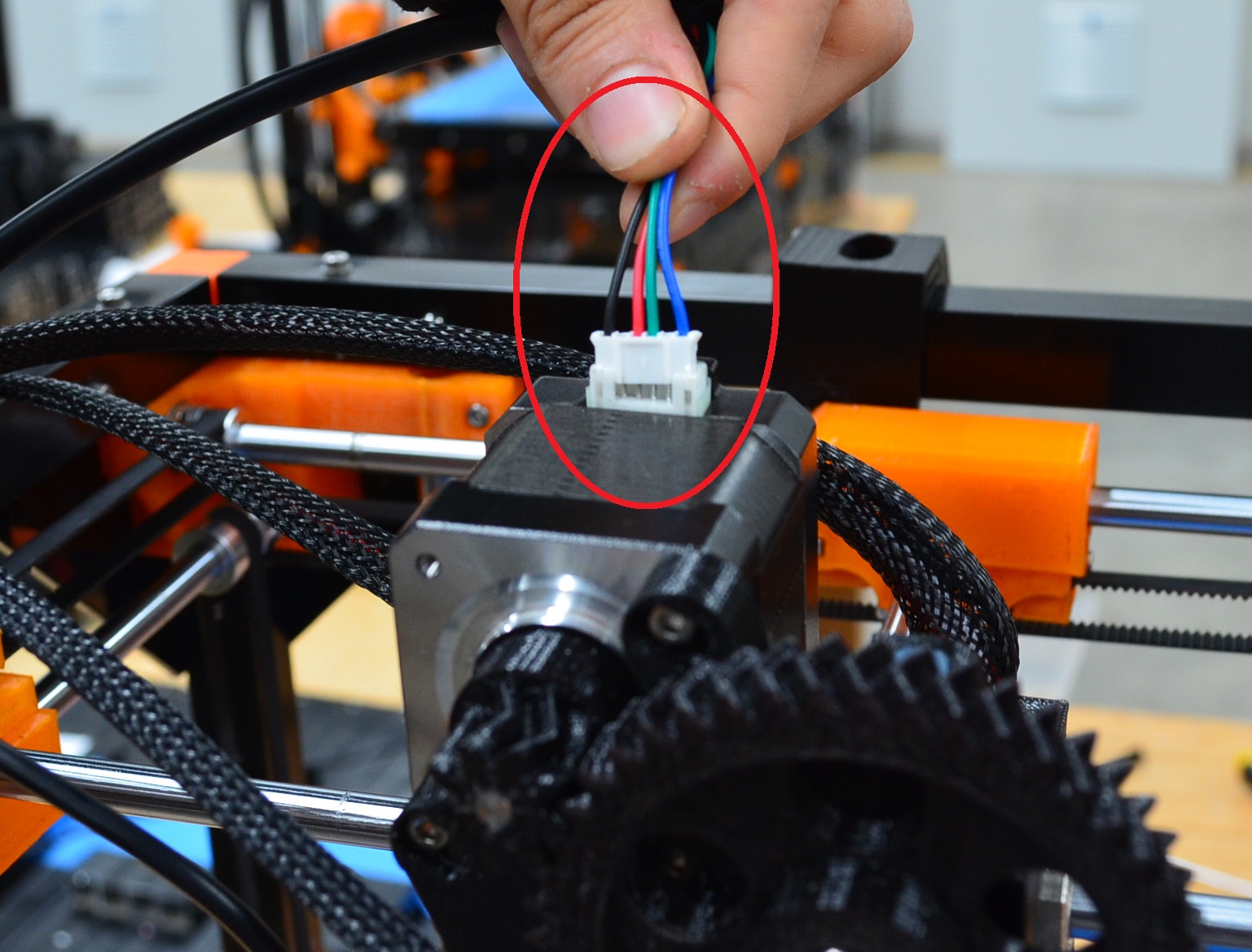
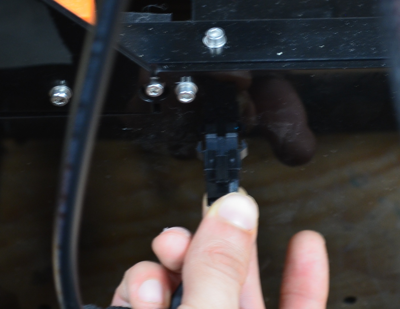
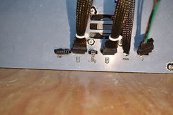
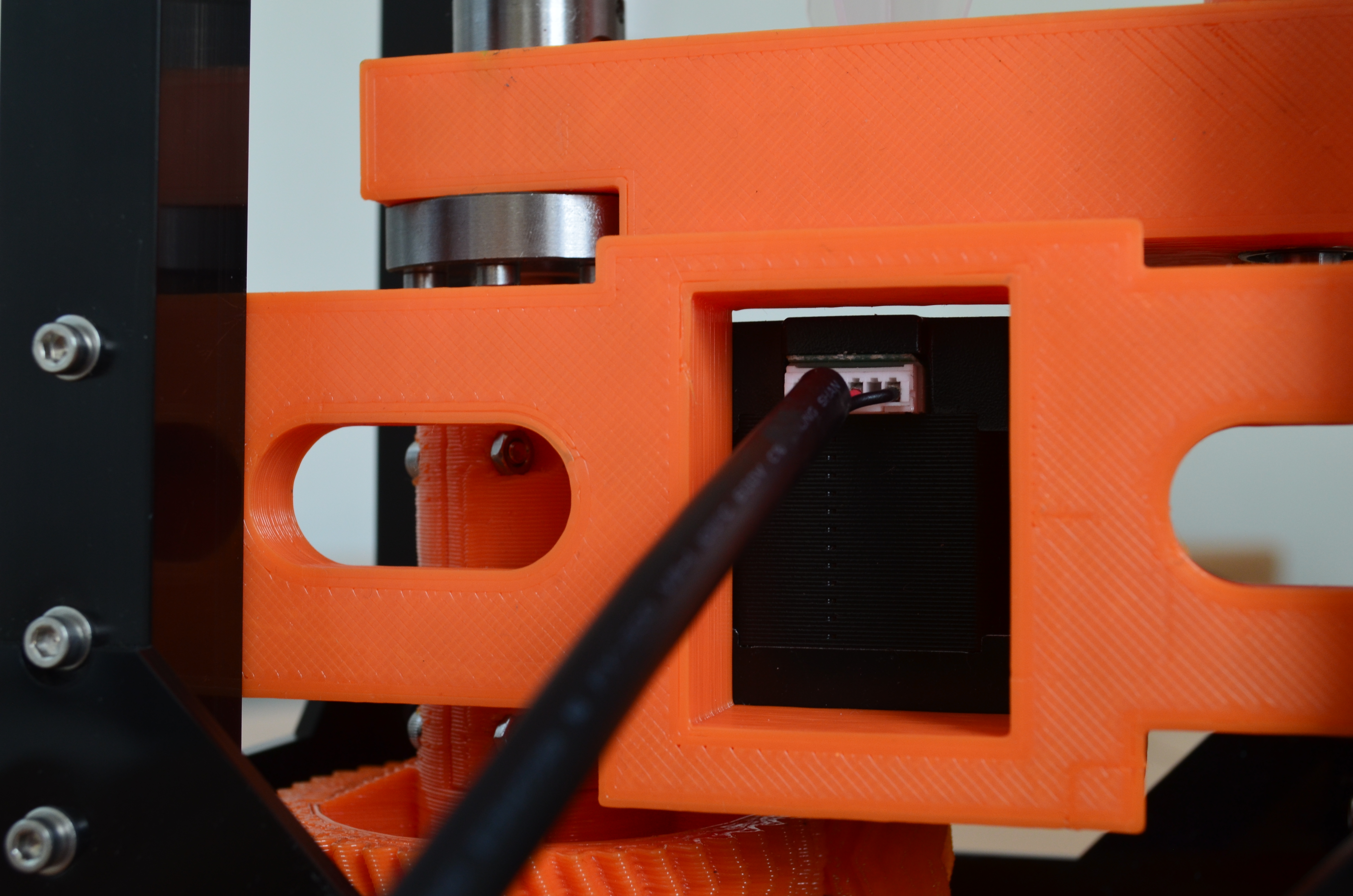
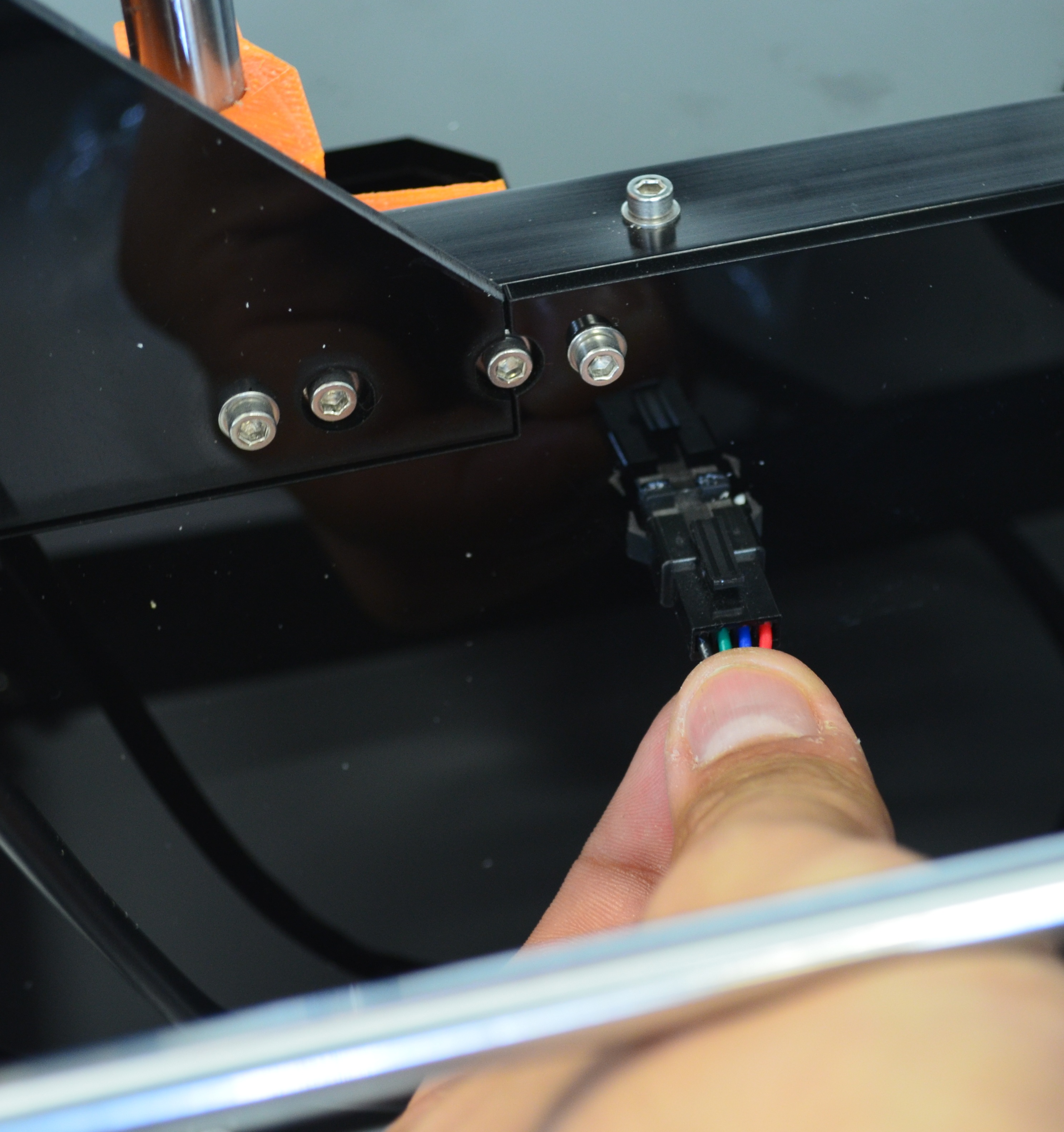
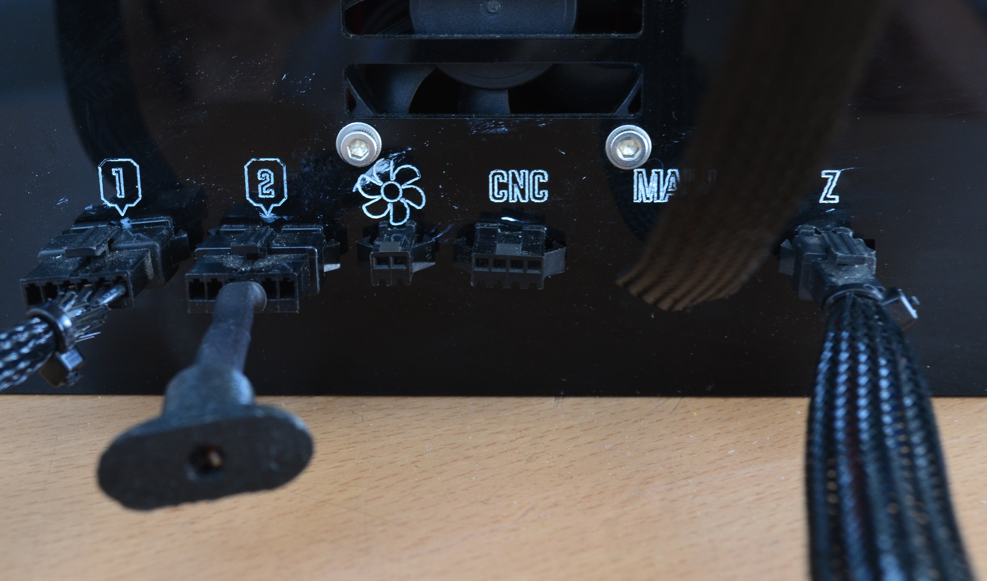
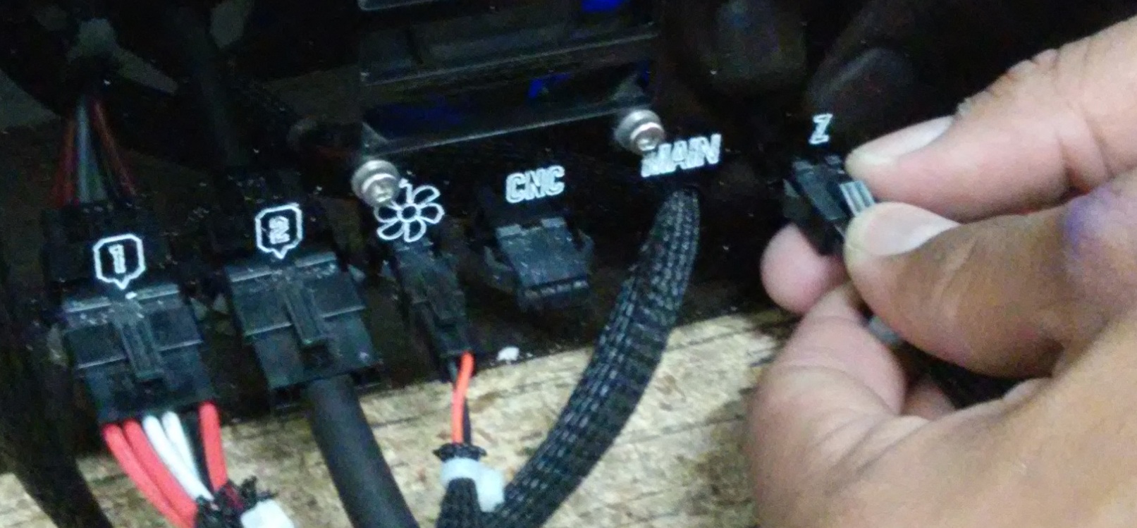
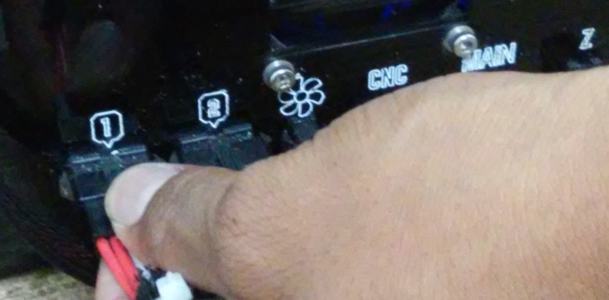
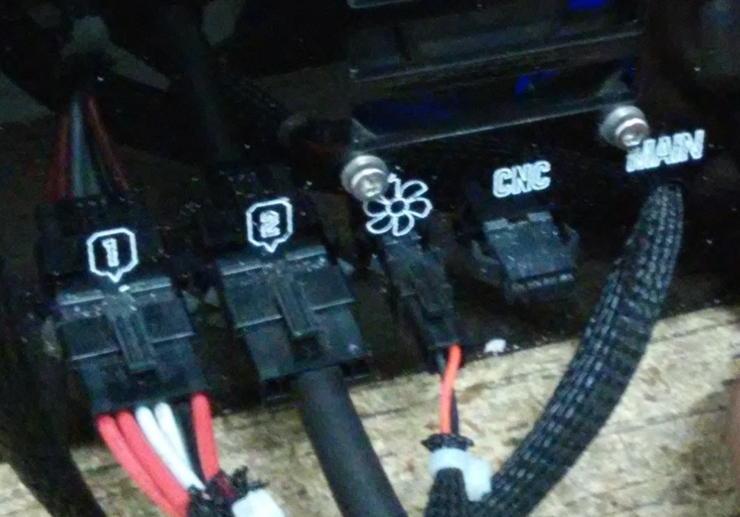
To ensure that the conexions were succesifully made, we must consider the following steps: First, we need to identify how any connectors are pluged in. there are 3 in total, as follows: 1.- the six pin connector must be pluged in the input with the number 1; 2 The two pin connector must be pluged in the input with the fan icon; 3.- The three pin connector, is the axis sensor, it must be plugged to the input with the letter Z.
Step 9
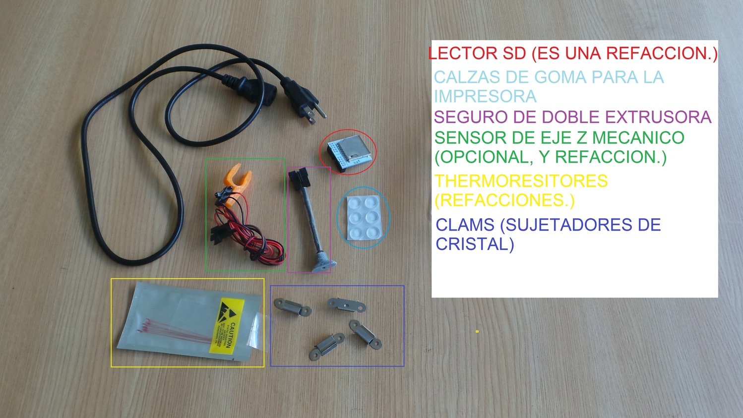
Now, lets review the accesories of the plastic box.
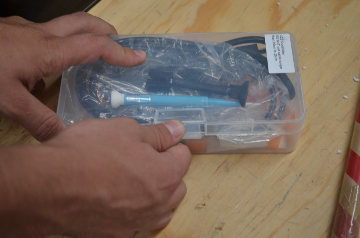
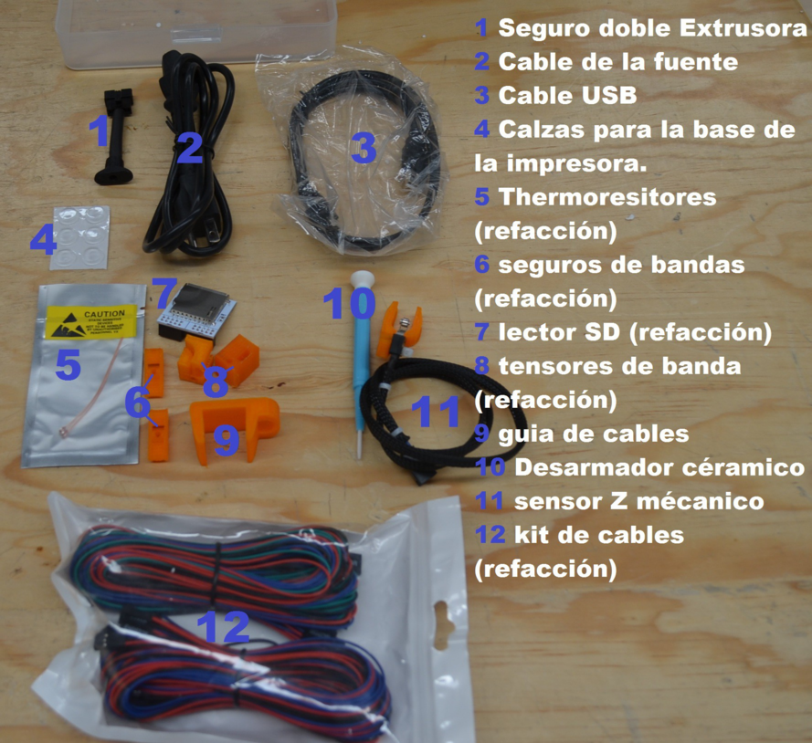
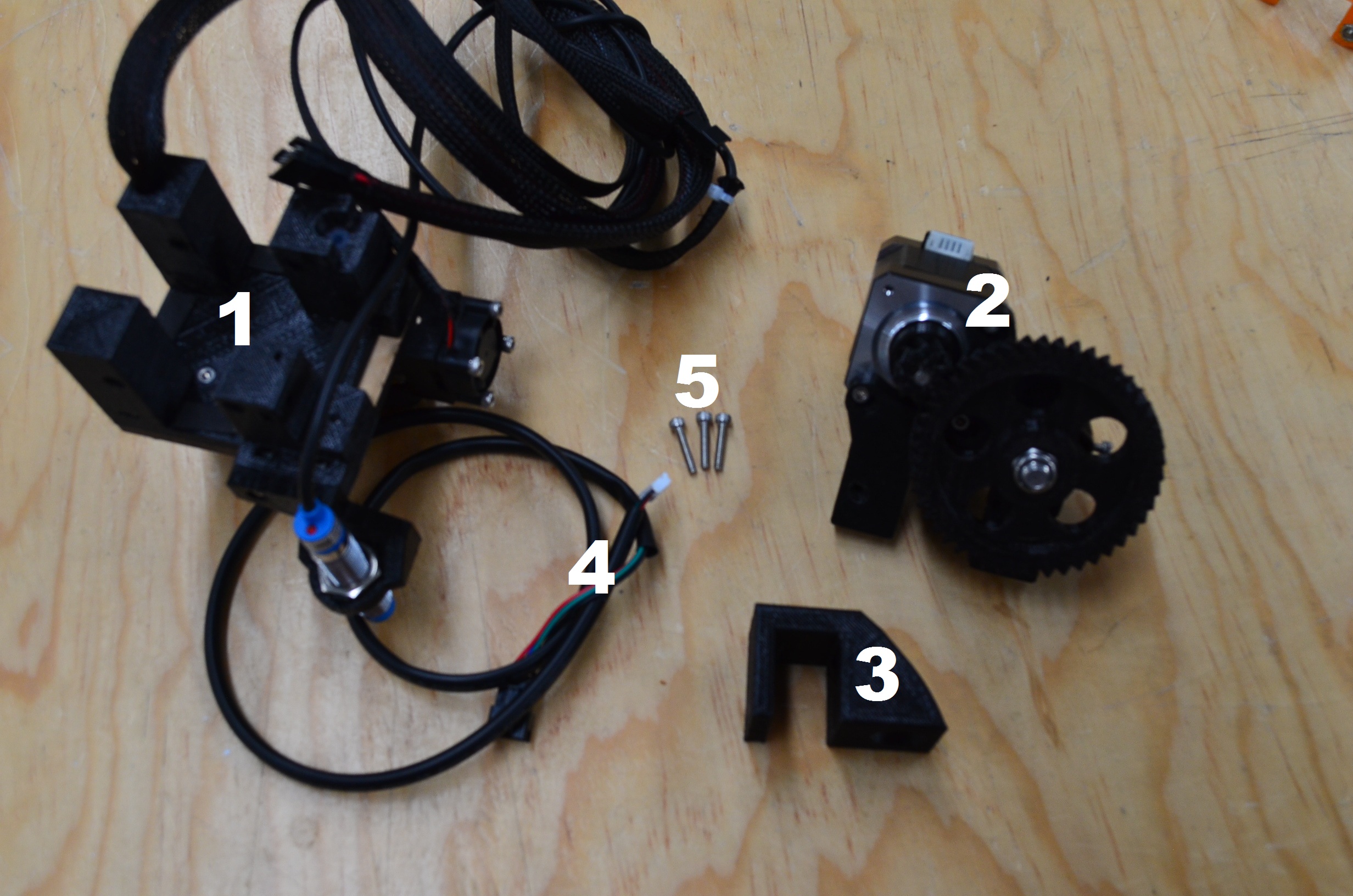
Get all the accesories out of the box, it should include all the components listed below and shown in the images.
1.-Dual extrusion clock 2.- Power cord 3.- USB cable 4.- Shims for the bottom of the printer. 5.- Thermistors (replacement) 6.- rubber belt holders (replacement) 7.- SD adapter (replacement) 8.-belt holders (replacement) 9.- Cable guide 10.-ceramic screwdriver 11.-mechanic Z sensor 12.-Cables kit.
Step 10
Is very important to plug the dual extrusion clock, the pins conector must be pluged with the input marked with the number 2. If we dont use this clock, the printer wll show an error or simply won’t work.
After all the connections are made, the printer should look like the image below.

Step 11
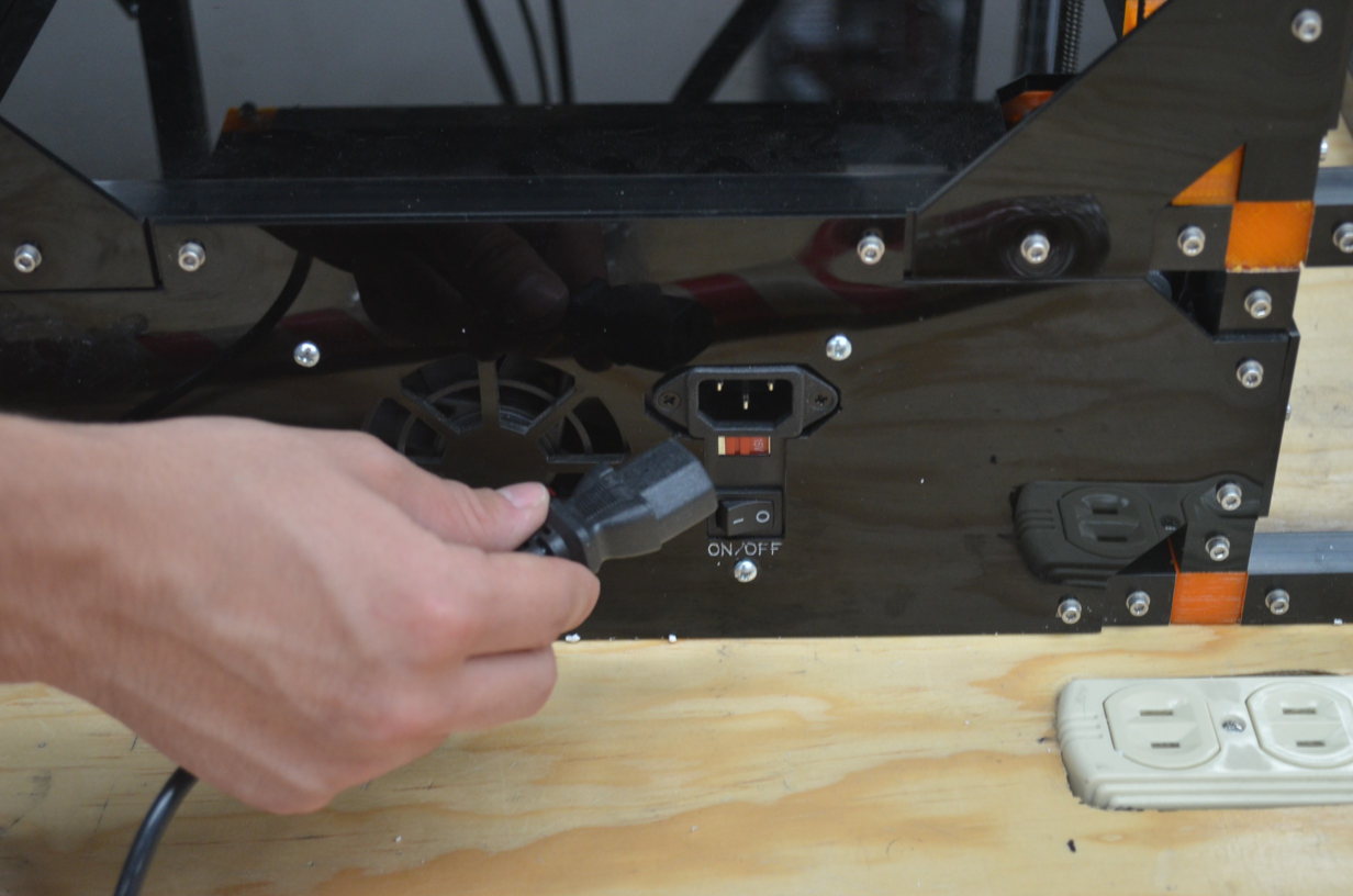
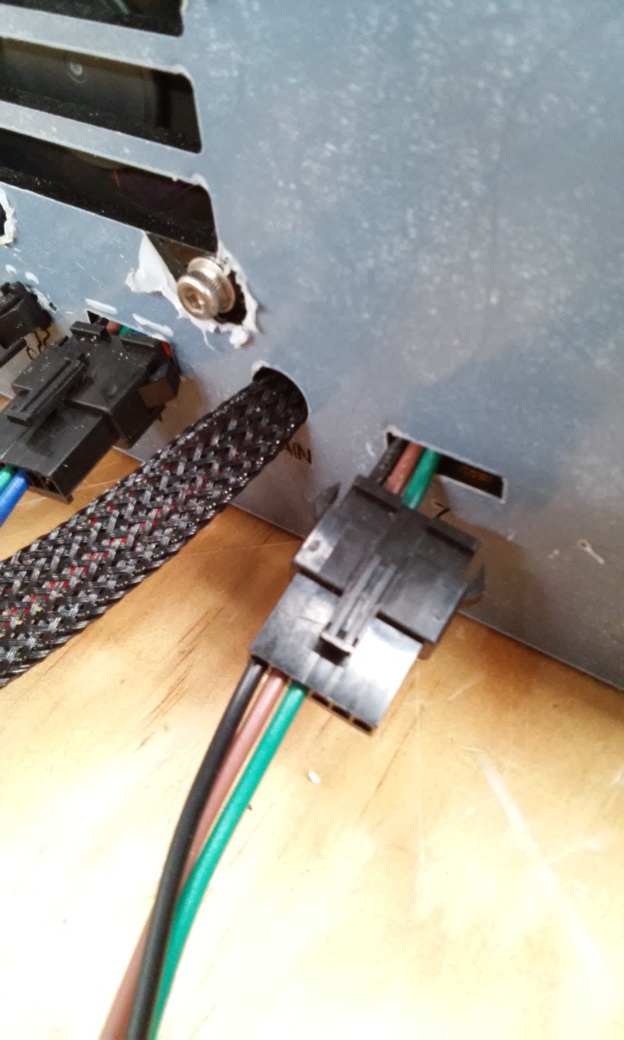
In this step we are going to put the final parts of the printer, we take the power cable and put it in the right side (always looking the front of the printer).
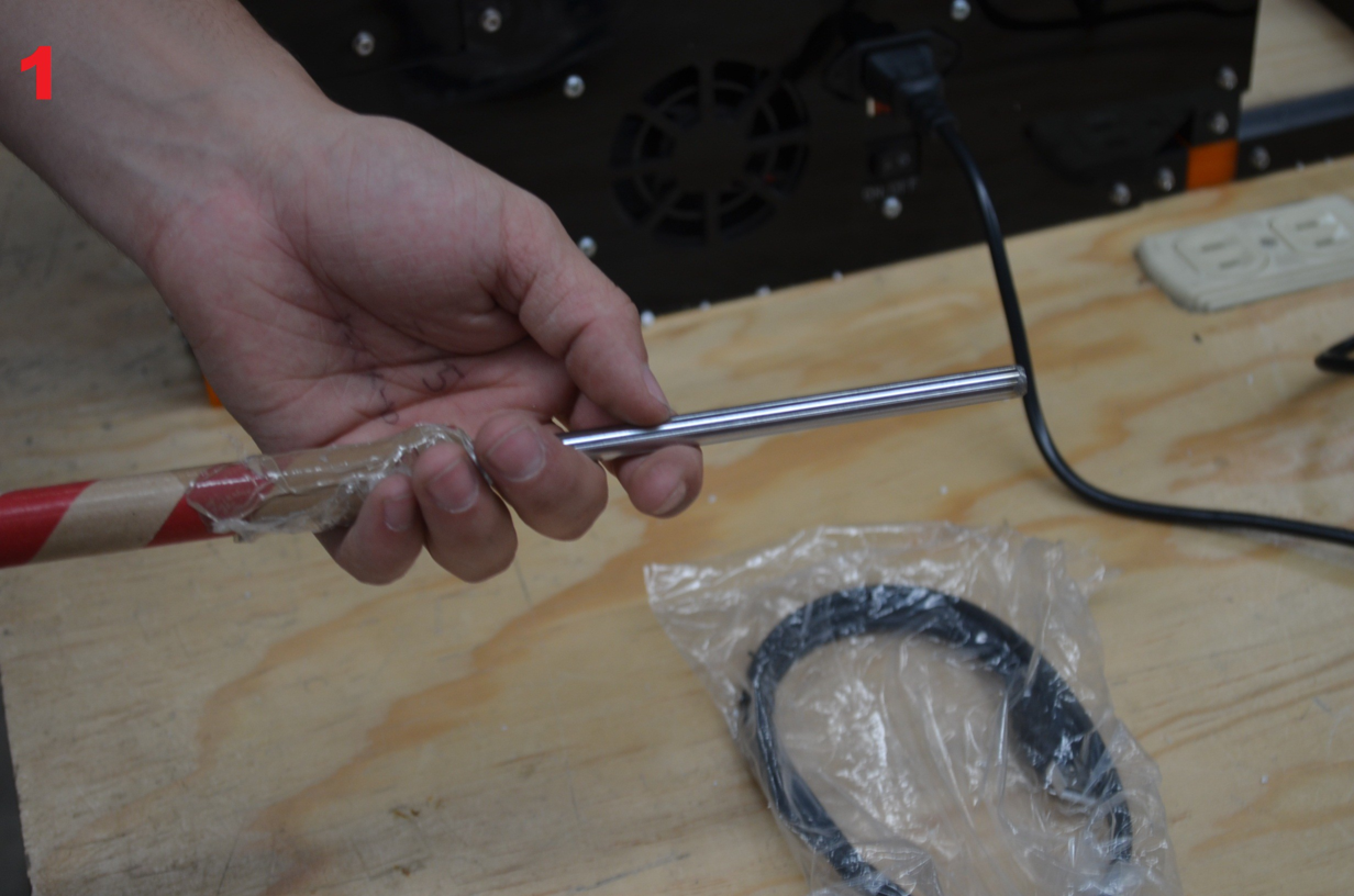
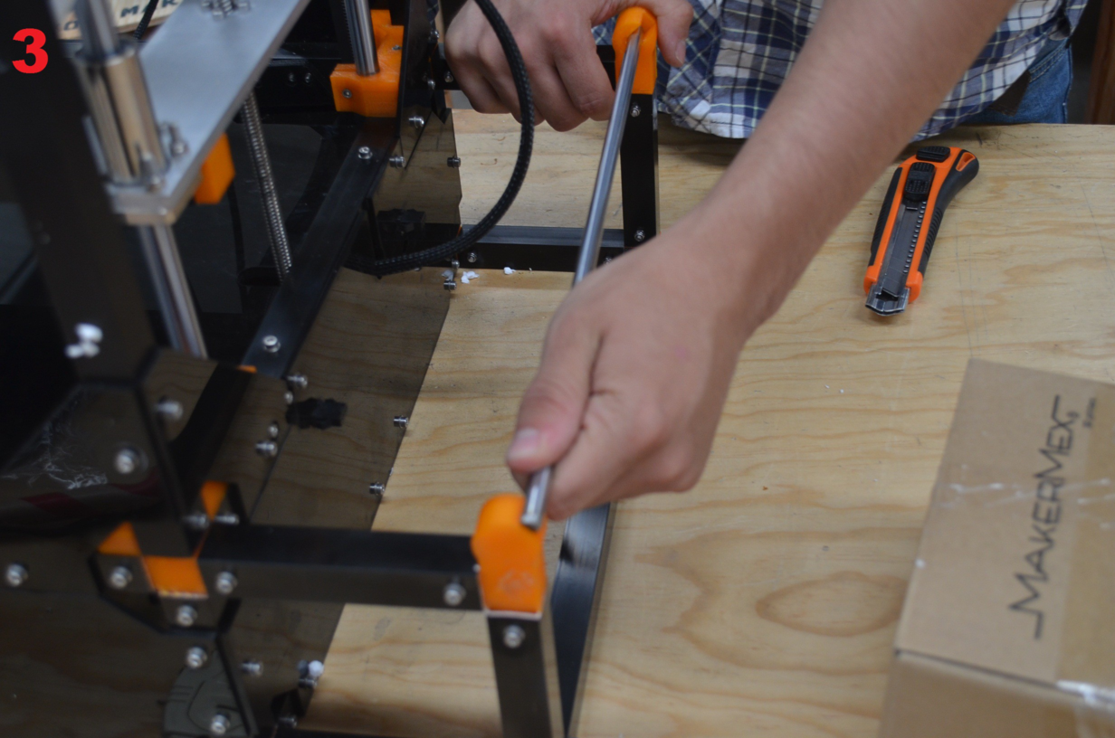
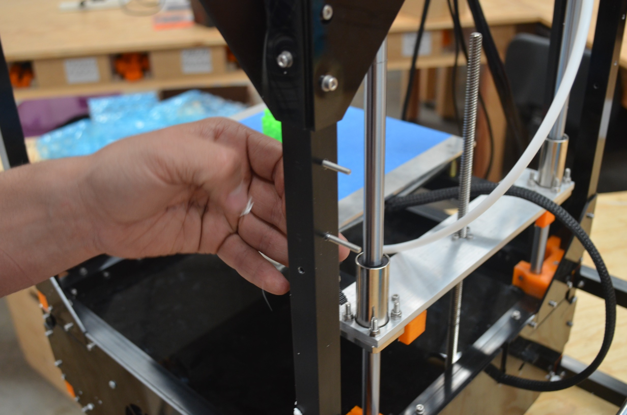
Now, we put the rod in the back of the printer, the rod originally should come in a paperboard package.
Step 12
Now we will put the cable guide, first we remove the support material with an utility knife. Use the images as reference to know where to cut.
Step 13
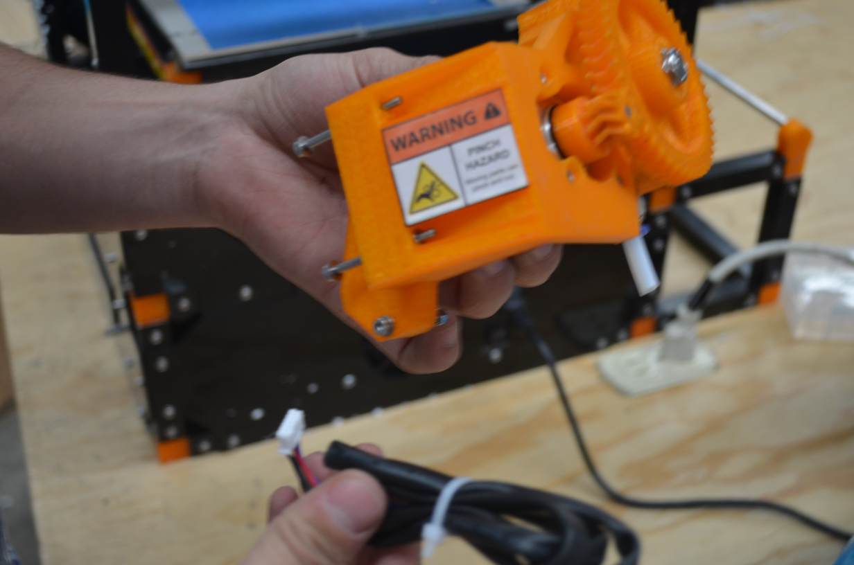
In these step we mount the extrusor, this part pushes the filament when printing, it must be located on the back part of the printer. To begin, we have to get ready with the box containing the extrusor.
First, unbox the mechanical part, it comes bubble wrapped, so you will need the utility knife again.
Once unwrapped, we will cut the plastic belt from the extruder wire and proceed to mount the extruder in the back profile, show the image for reference. Before mounting, you can show the screws out of the extruder, remove them, now identify the holes where the pice will be placed, and then, put the screws.
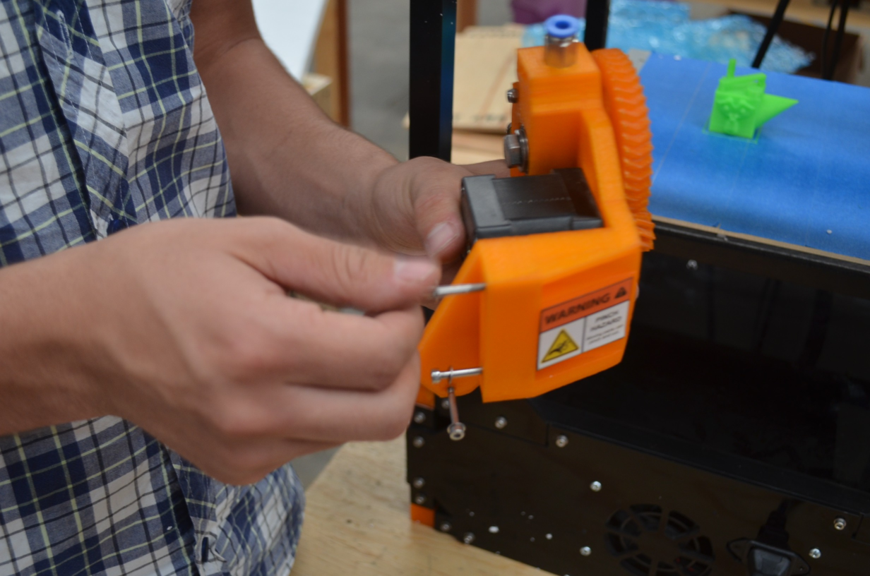
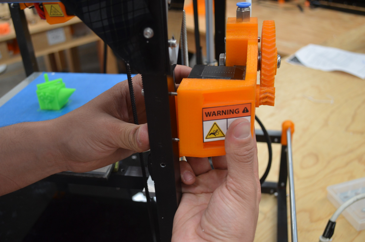
With a 2.5mm allen wrench we will hold the nuts and we will screw, you can see the images as reference. we need to screw the 3 screws to hold it firmly the extruder.
Now we connect the extruder motor. connect one side of the cable to the extruder and the other side in the back of the printer, use the images as reference.
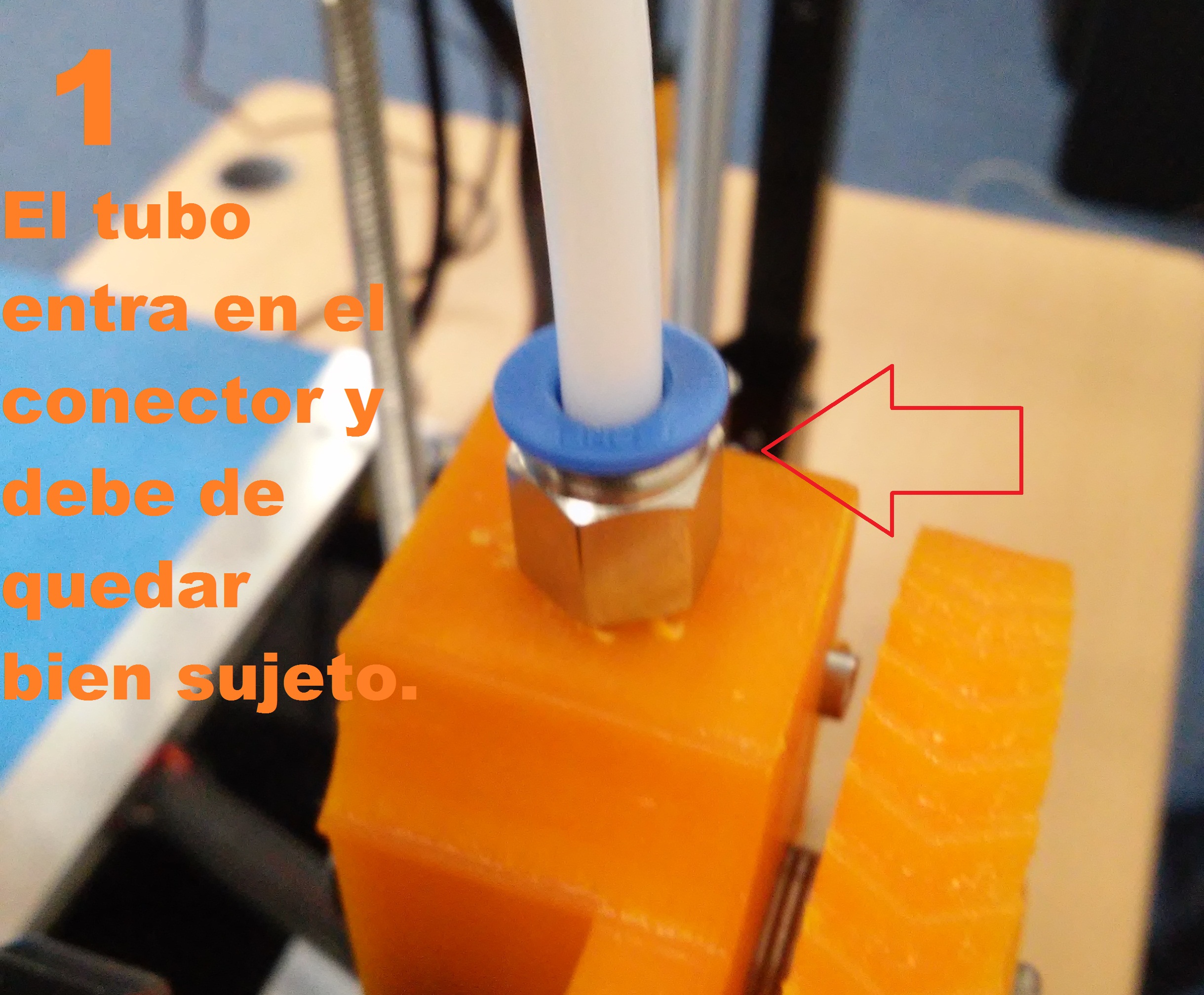
Now plug the bowden tube in the blue part of the connector pressing it down to hold it. now we can reviwew the connection pulling up the tube, it must remain connected.
Step 14
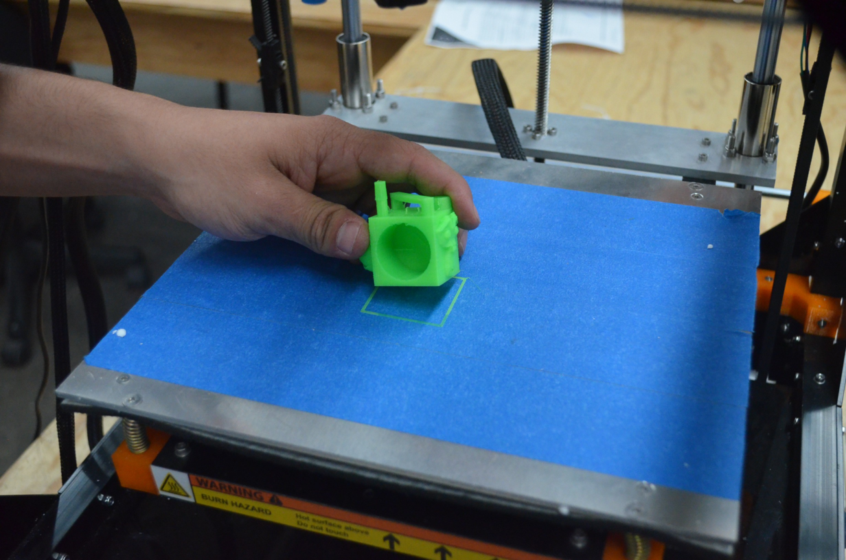
Remove the example printed part from the printing plate, for this step you may need a knife, it is possible to remove the piece by simply pulling it up, i it is sticked to strong, then use the knife.
Step 15
After being removed the printed piece , identify the SD card slot, the SD card is where we will save the gcode with instructions for the printer.
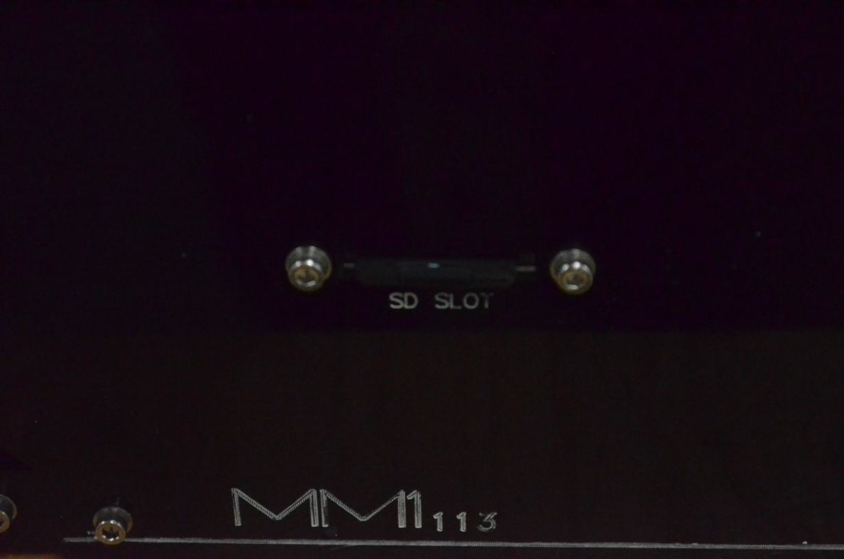
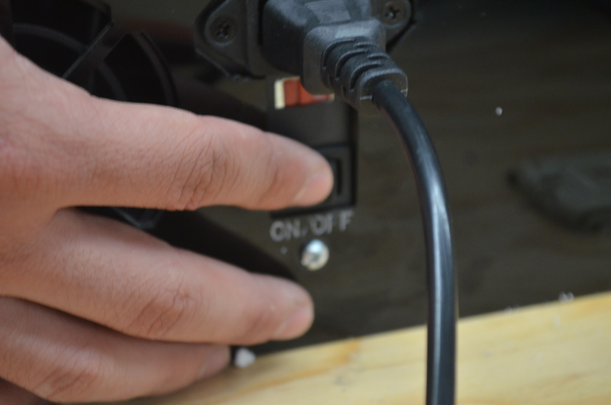
Lastly, connect the power cable and turn the printer on.
You can watch the following video to review the past steps more clearly.
My First Print
In order to make your first print,you have to download a 3D modeling software to generate an STL file, we recommend Blender.
What is Blender?
Blender is a 3D modelling speciallized software, that also have another features like animation, game programming features, this software uses various techniques, like node processing, digital painting, and digital sculpting.
What is an STL file?
Is a file format for computer assisted design (CAD) that defines 3D bjects geometry, excluding color, textures and other physical properties that other formats includes.
Once you have your STL file, you must geerate a G code that can be read by your printer.
Cura 15.01 is the software you will use to get G code from your STL.
Al the software we use is oopen source, that means that you dont need to pay a license to use it, also you could download and modify the source code to extend the functionality.
Software downloads
-Software Cura

Here is the download link, we strongly recommend 14.12 version.
https://ultimaker.com/en/products/cura-software/list
-Pronterface Software

Here you have the download link
http://koti.kapsi.fi/~kliment/printrun/
Blender -Software
Here you have the download link
Cura installation and setup for the MM1
Step 1
We suggest that download Cura from our website, there you wil find a link to the recomended version.
Note
This link is in the “help/manuals” section, go to any manual and then go to software downloads.
Start the Cura instllation
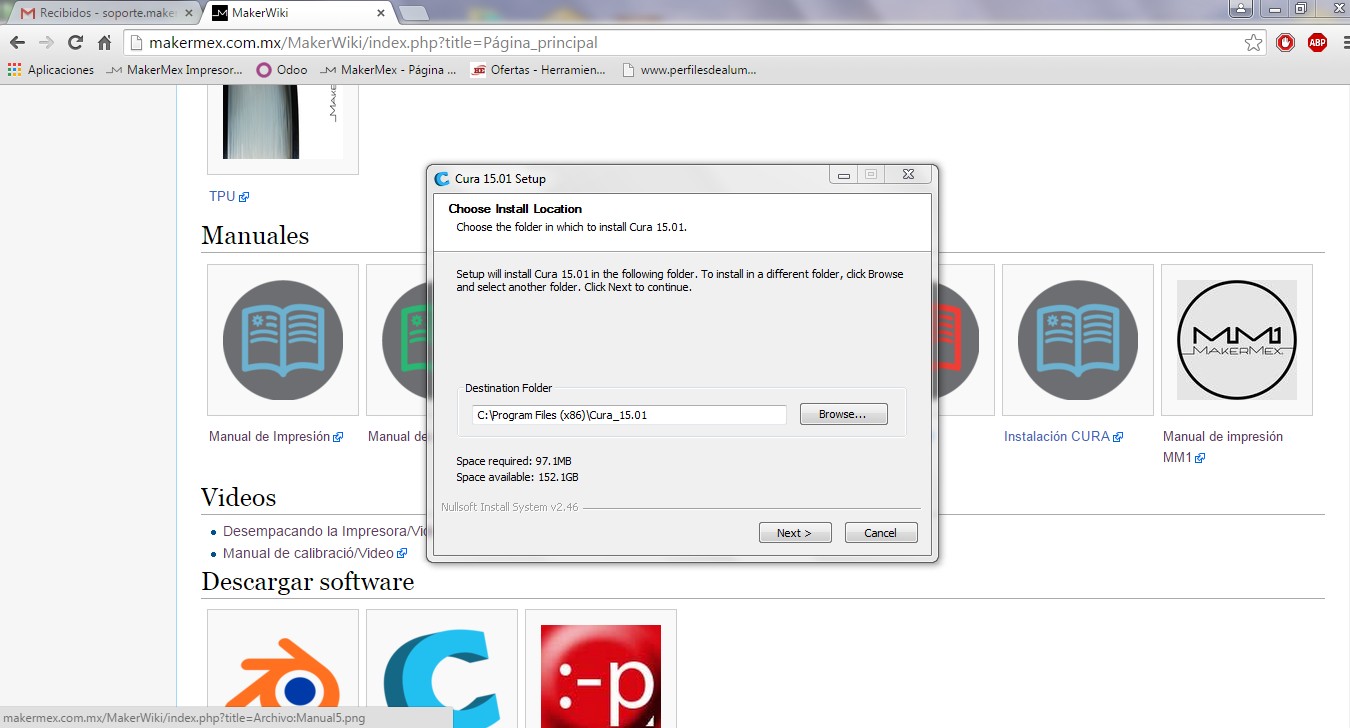
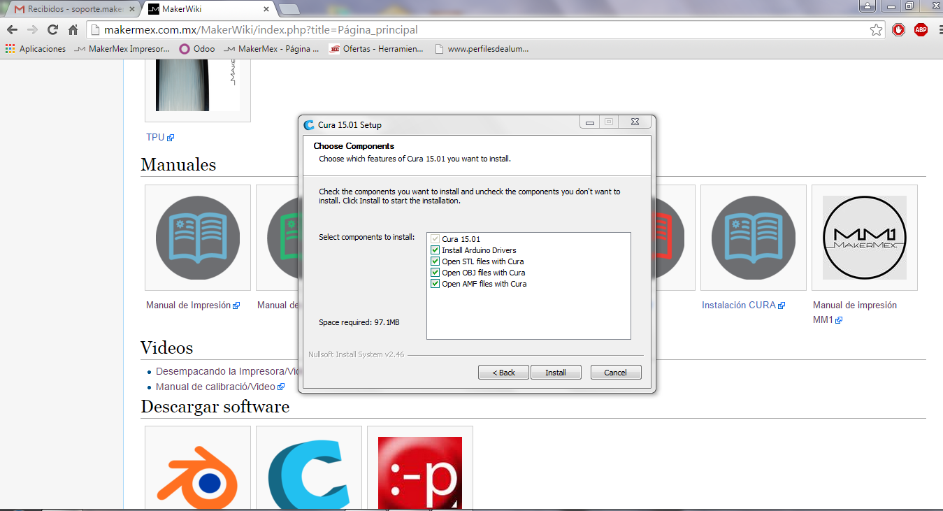
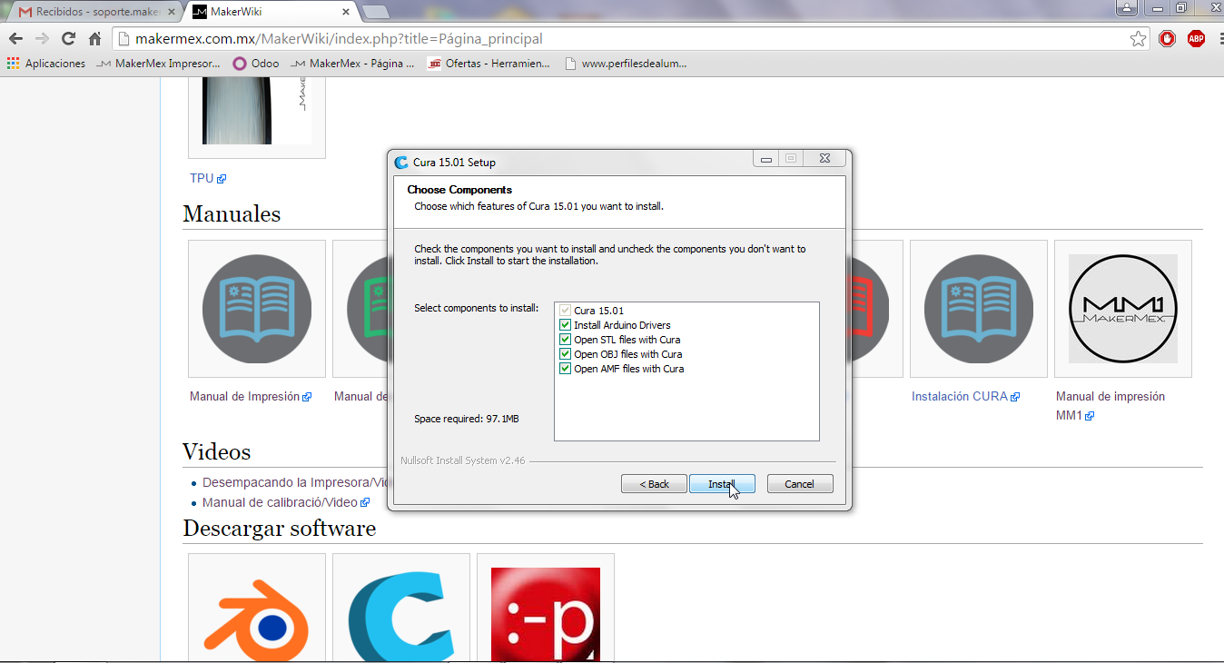
Step 2
Select the files that you want to open and click om install. we recommend the options shown in the image.
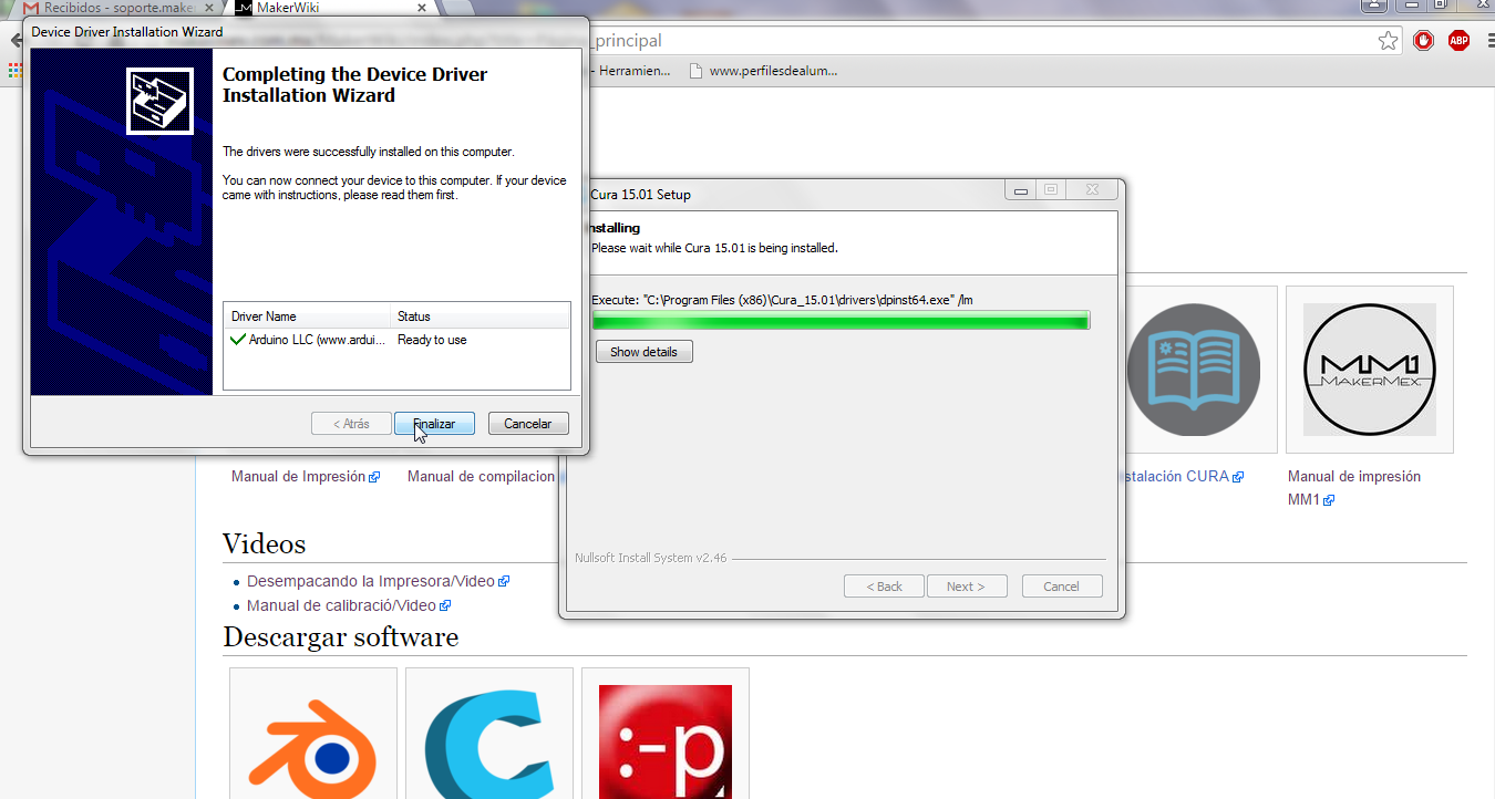
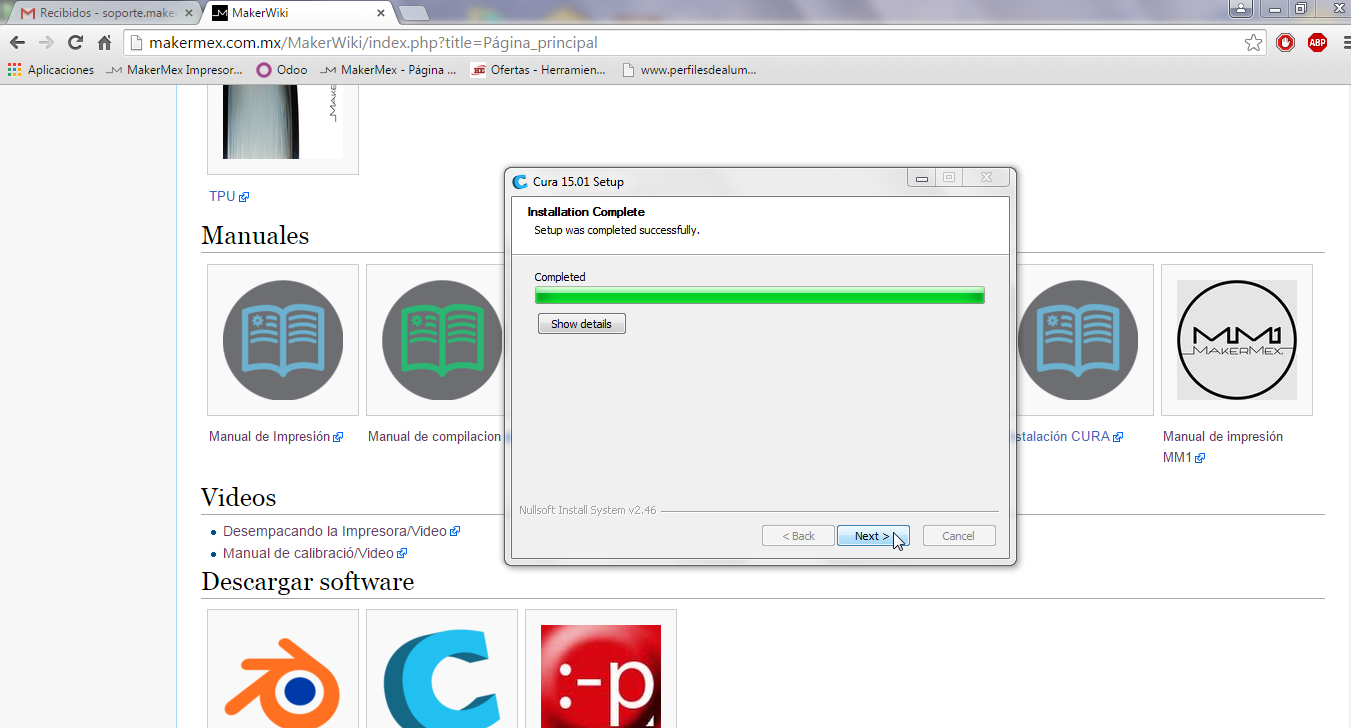
Step 3
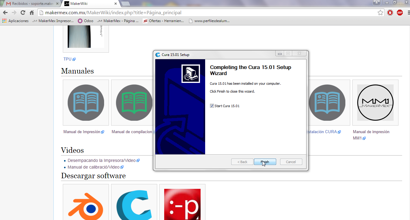
After the installation of the software, click “next” on the setup window and then “Finish”
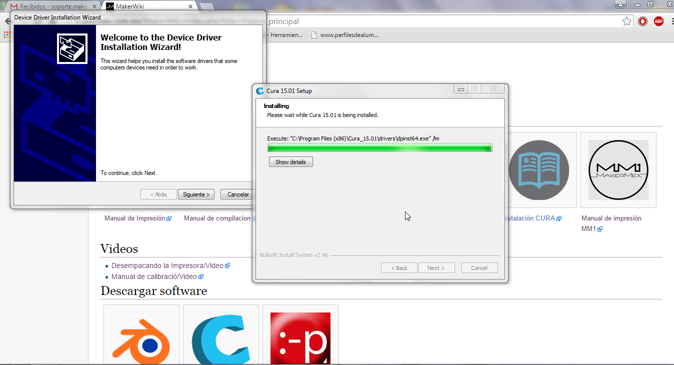
Step 4
In the window, click on “next” and then “finish”.
Step 5
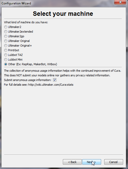
On the lnguage selection window select “english” and click next. On the next window select “other” and click “next” to begin filling the printer configuration.
Step 6
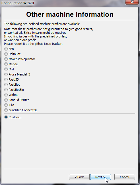
On the next window select the option “custom”, then click next.
Step 7
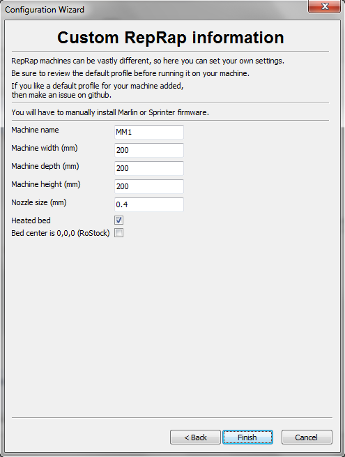
On the next window fill the information of the image, this part refers to the prnter dimentions and if t have hot bed. also you will note the option to change the center of the printer, we will leave this option as 0,0,0. After that, click “finish”.
Step 8
You will see this window
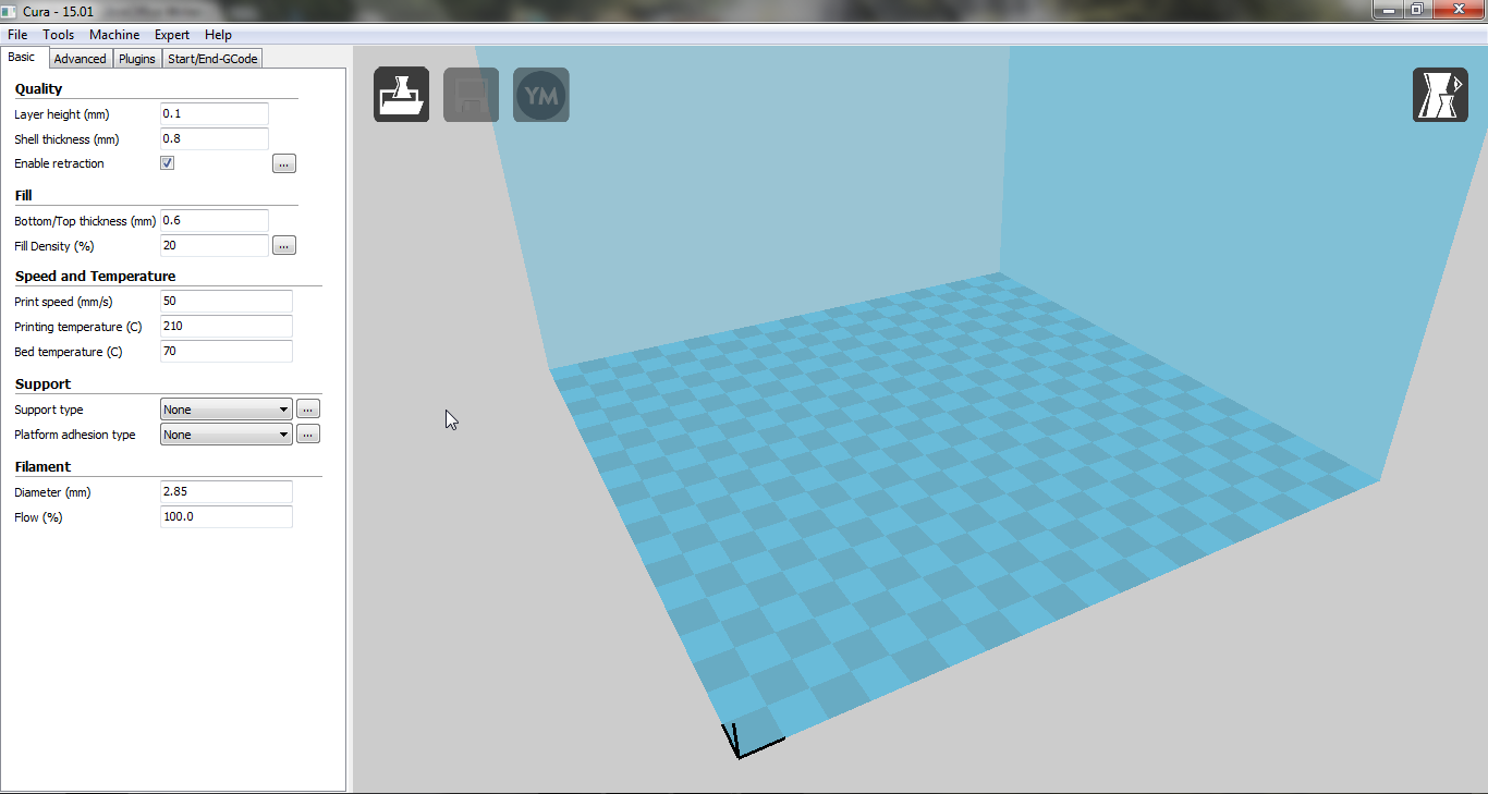
On the next windows we configure the printing arameters, usuallywe only modify the “basic” and “advanced” tabs.
Step 9
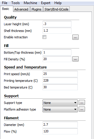
Configure the basic tab as follows:
| PLA temperature 200°C to 212° |
| Hot bed 40°C to 60°C |
| Temperature for ABS 225°C |
| Hot bed 97°C |
| Fill Density |
| This vaalue depends on each piece, a density of 0 to 20% will be a weak piece. |
| The recomended density is between 25% to 40% |
| Use 45 to 60% infill density for strong pieces |
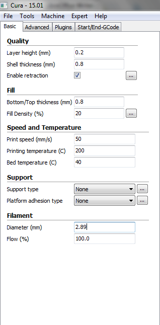
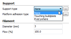
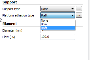
This boxes are used to select adhesion platform and support type
Step 10
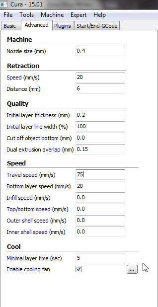
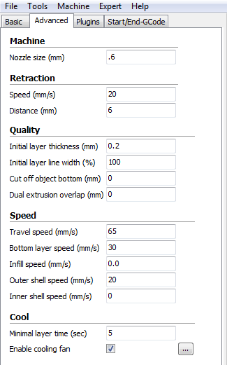
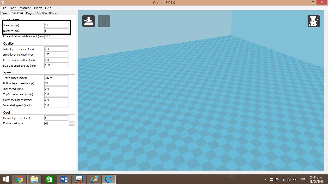
In advanced taab we recomend to configure retraction to 6 or 8mm. Configure the other options as shown in the image.
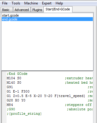
Note
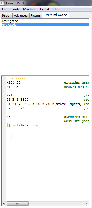
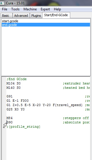
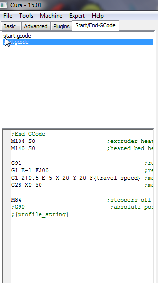
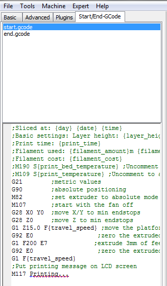
Lastly go to start/end gcode tab will type a semicolon “;” before G90 to comment that line.
Printer connections
In this manual we can observe the correct connectons of our 3D printer, is very important to follow the indications. The image shows the contents of the plastic box.
Step 1
Connect the single module to the conections cart. the output of the modue is a 6 pin connector that must be plugged to de input marked with number 1 as shown in the image.
Step 2
Connect the inductive sensor for the Z axis, it has a 3 pin connector that must be plugged to the inut marked with letter “Z” as shown un the image.
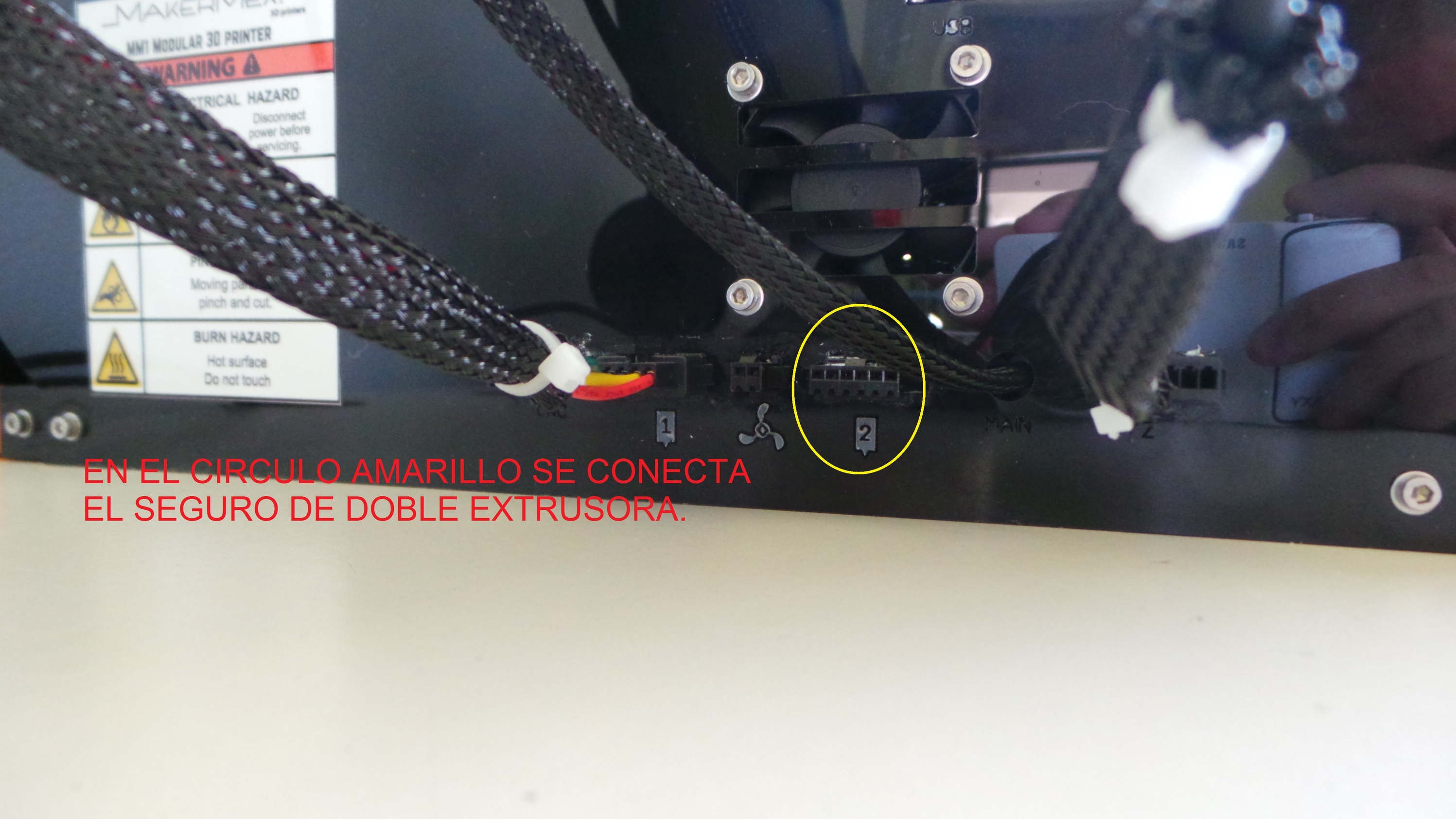
Step 3
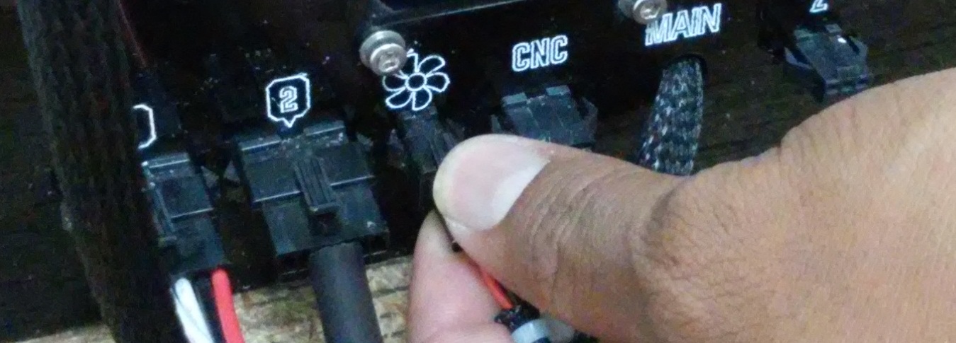
Plug the dual extrusion clock
Lets plug the dual etrusion clock in the input with number 2, if you use dual extrusion module you must remove this clock.
Note
If only the single module is connected and the tumbler is not connected, the LCD screen will show “Error Mintemp (in printers before 198).
From the 3D printer with serial number 198 and above, dual extrusion tumbler is not necessary for the machine or any module, and is not included, this feature is now included in the controller firmware; if the
serial number of your machine is lower than 198 and you want to update
the firmware please contact our support team via the forum .
Step 4
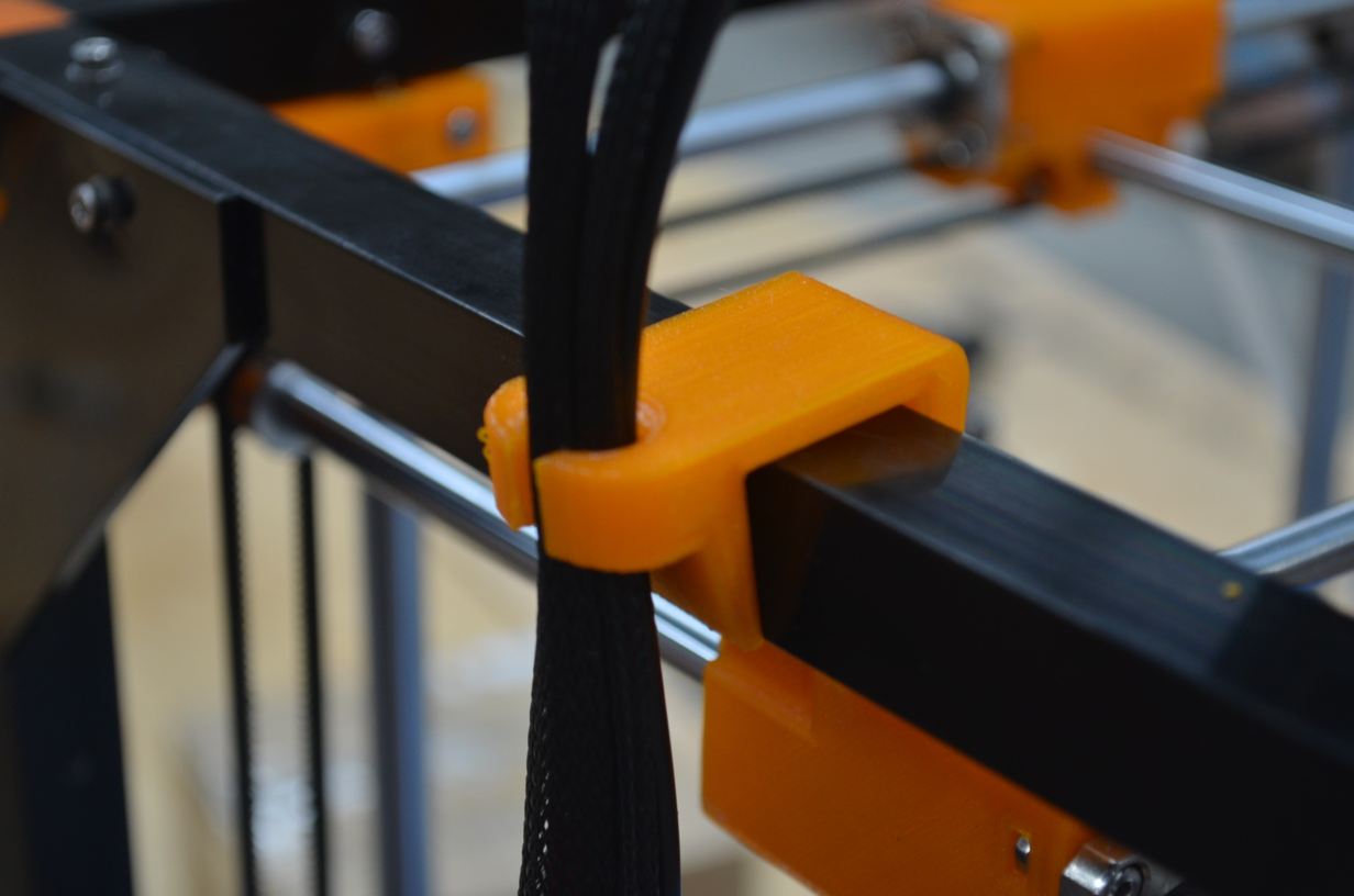
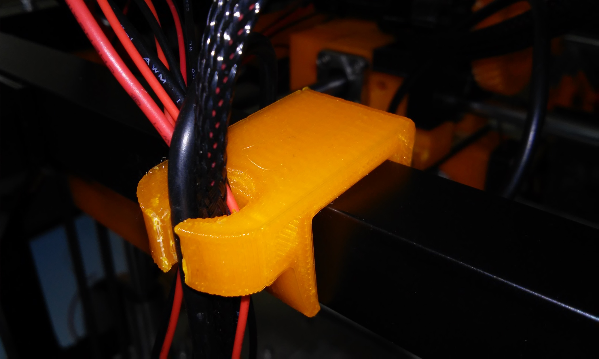
Mount cable guide
The plastic piece inside the plastic box must be mounted as shown in the image, it is ued to mantain the wires in place when printing.
Step 5
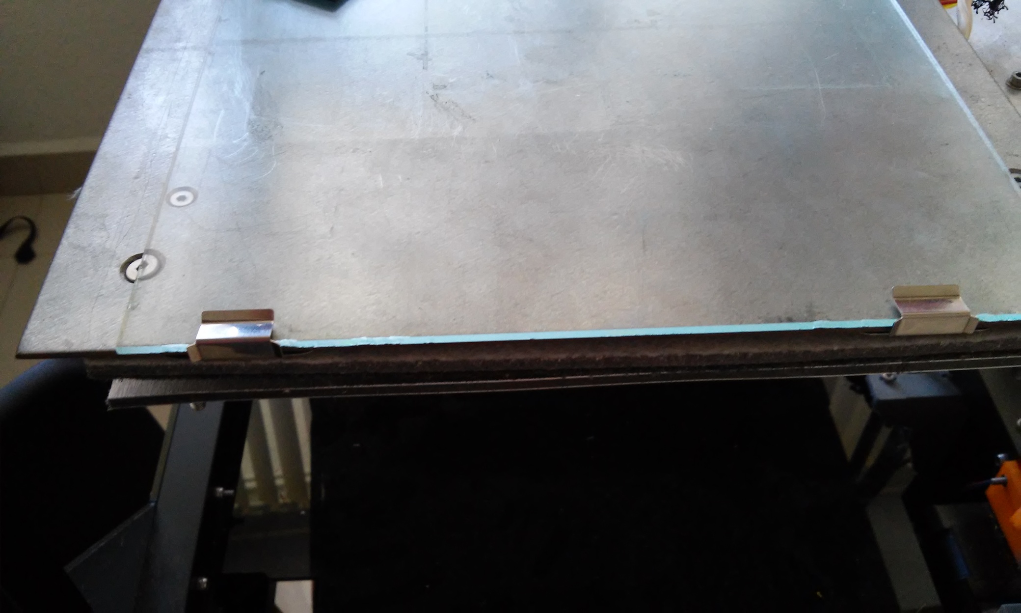
How to put the clamps and the glass
th clamps are the holders of the glass in the metal plate, put them as shown in the image.
MM1 V1.5 3D printer connections
Here we can observe how to connect our 3D printer, is very important to follow the indications.
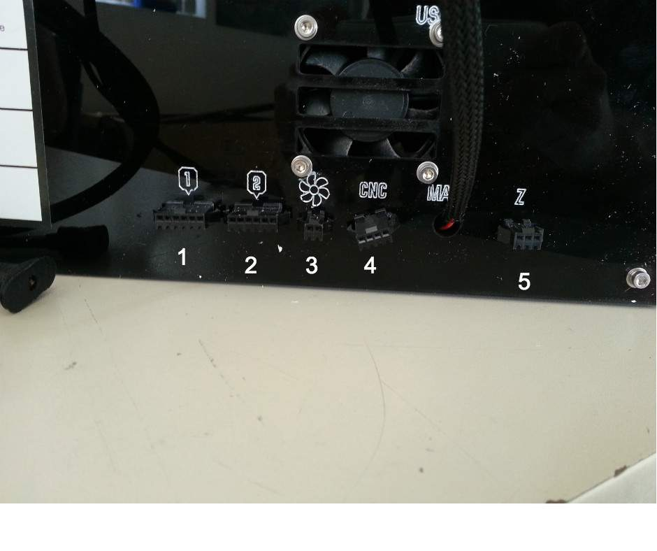
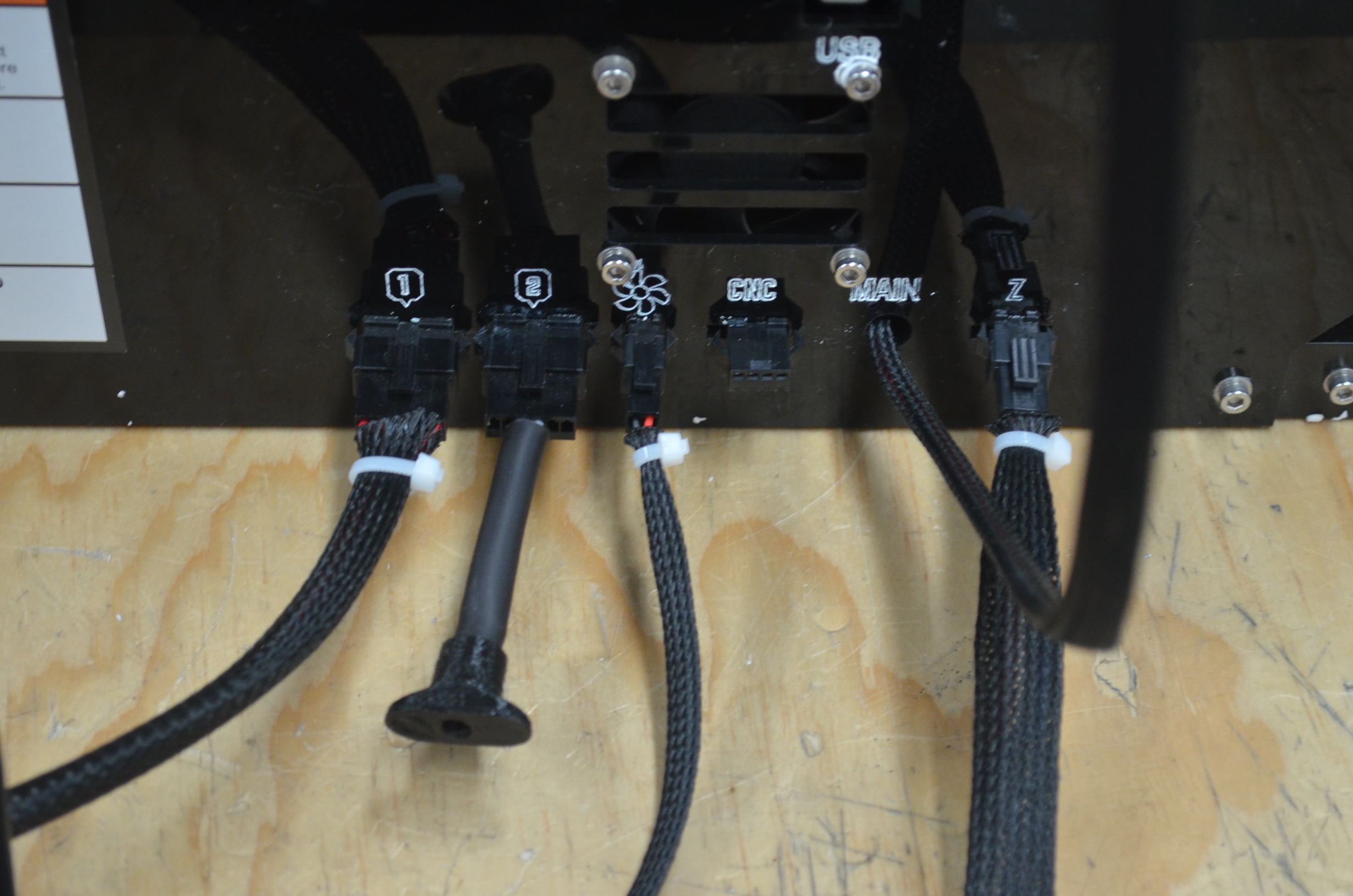
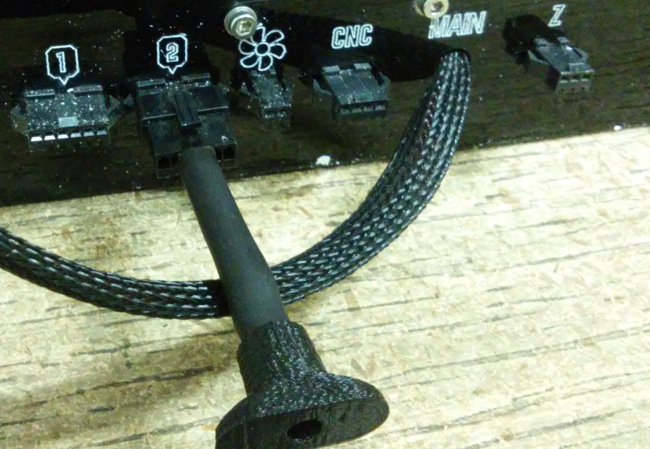
First identfy the conectors
| Connectors |
| 1.- Extruder #1 |
| 2.- Extruder #2 |
| 3.- Cooling fan |
| 4.-CNC Module |
| 5.- Z sens |
Single module connection.
To be able to print with the single module (included by default), you need to connect it this way.
Note
When printing with this module is very important to have the dual extrusion tumbler connected, if this tumbler is not plugged in is impossible to print (printers with serial number before 198)
Note
From the 3D printer with serial number 198 and above, dual extrusion tumbler is not necessary for the machine or any module, and is not included, this feature is now included in the controller firmware; if the serial number of your machine is lower than 198 and you want to update the firmware please contact our support team via the forum .
Usage of the screen
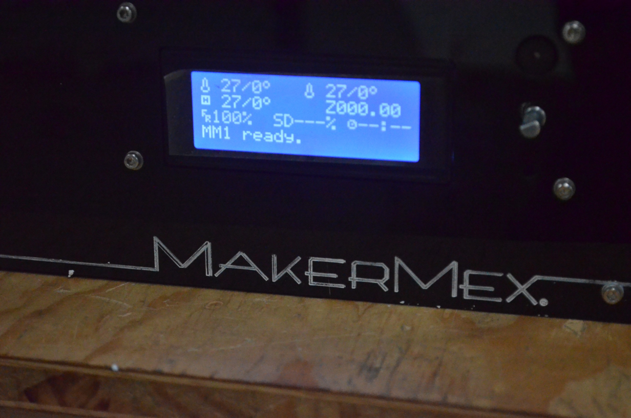
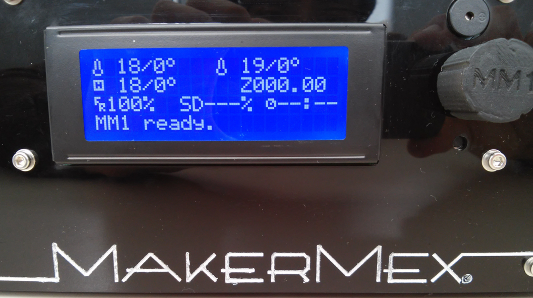
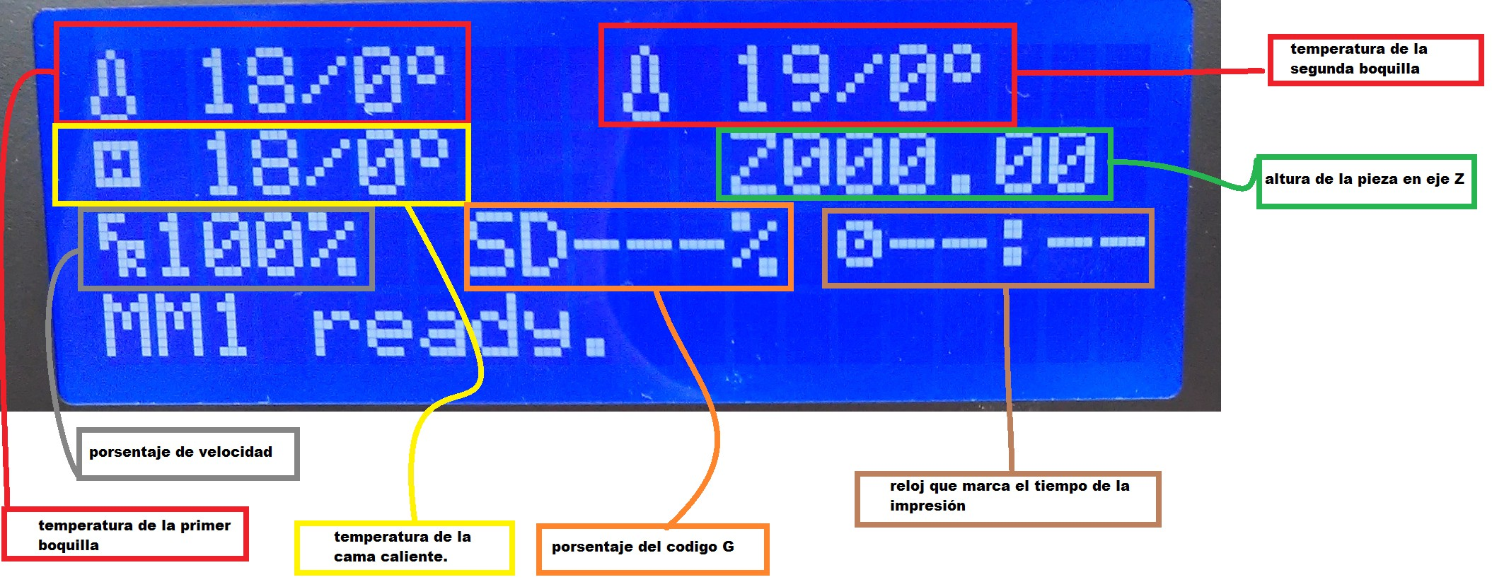
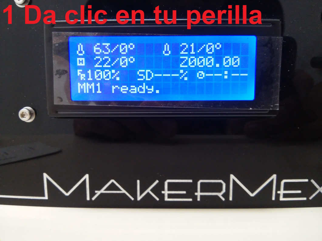
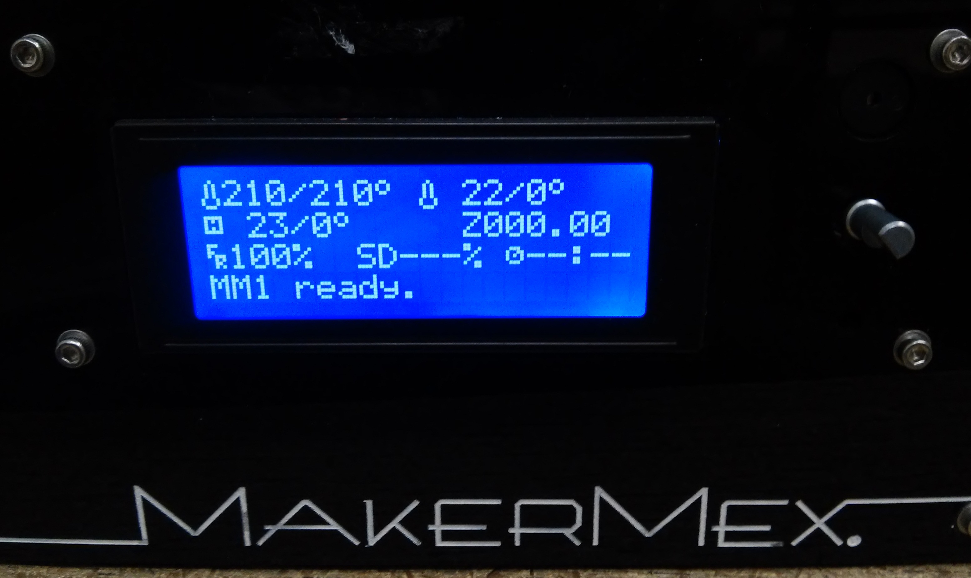
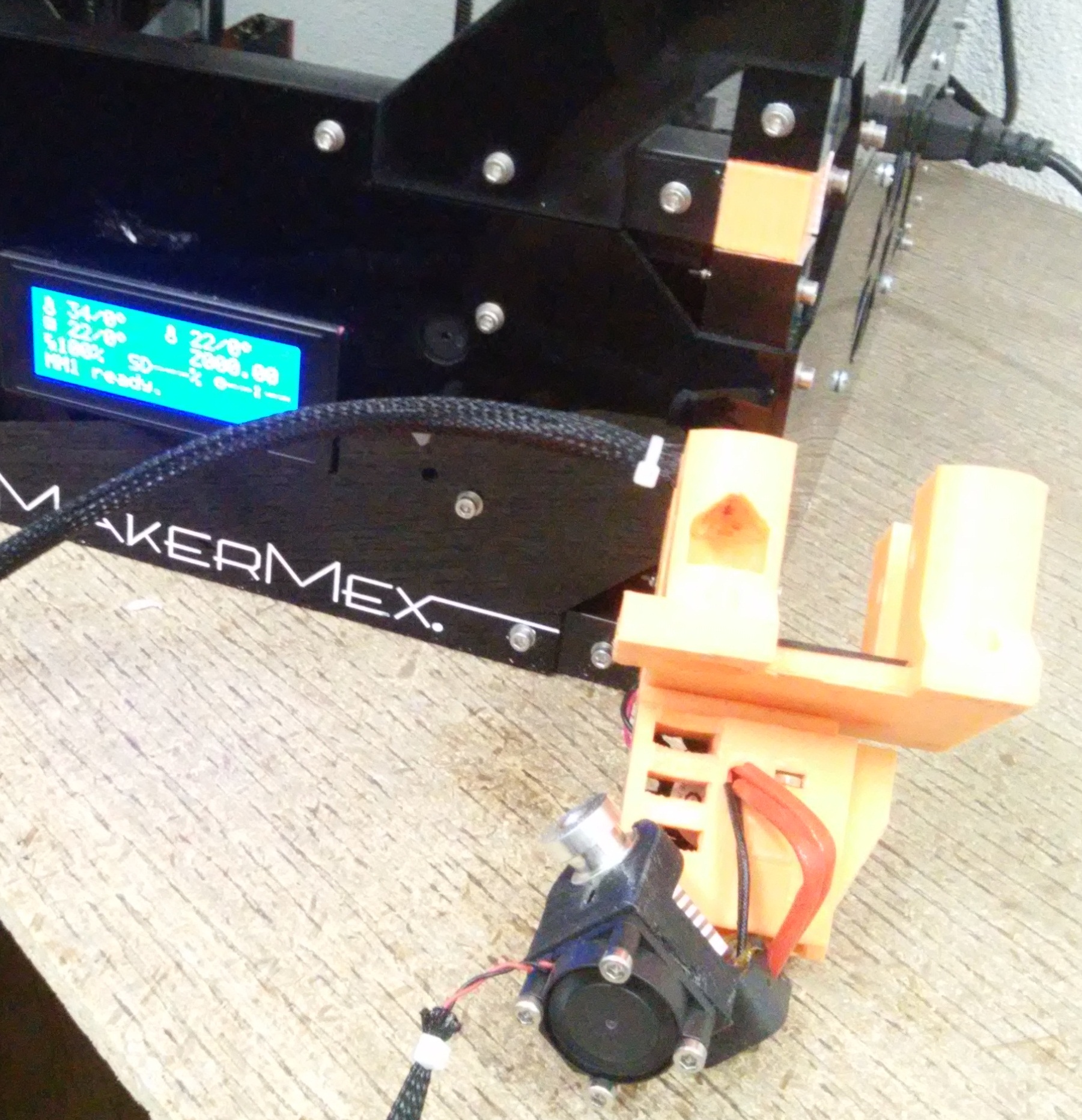
After you start the 3D printer you will see the main screen of the LCD where you can find all the printing information.
| Information of the screen |
| Noozle temperature |
| Noozle of the second extruder (if installed) |
| Hotbed temperature |
| Printing time |
| Printing progress percentage |
| The printing seed in percentage |
| A pre-configured message |
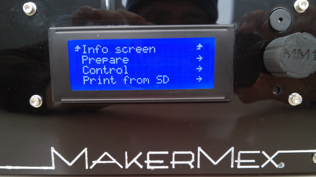
- The LCD screen has a multifunction knob that you can turn and press.
- To enter a menu on the screen simply select it by turning the knob and then press it.
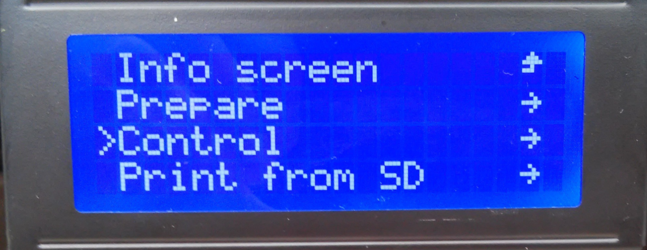
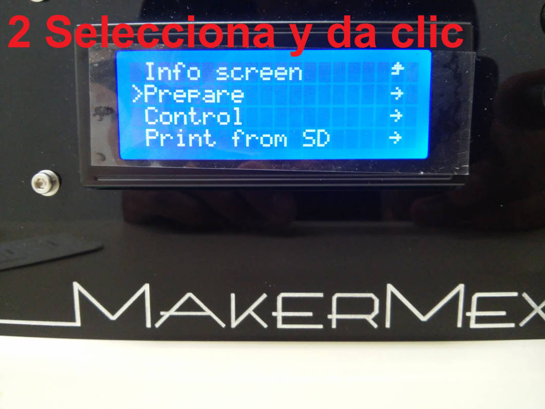
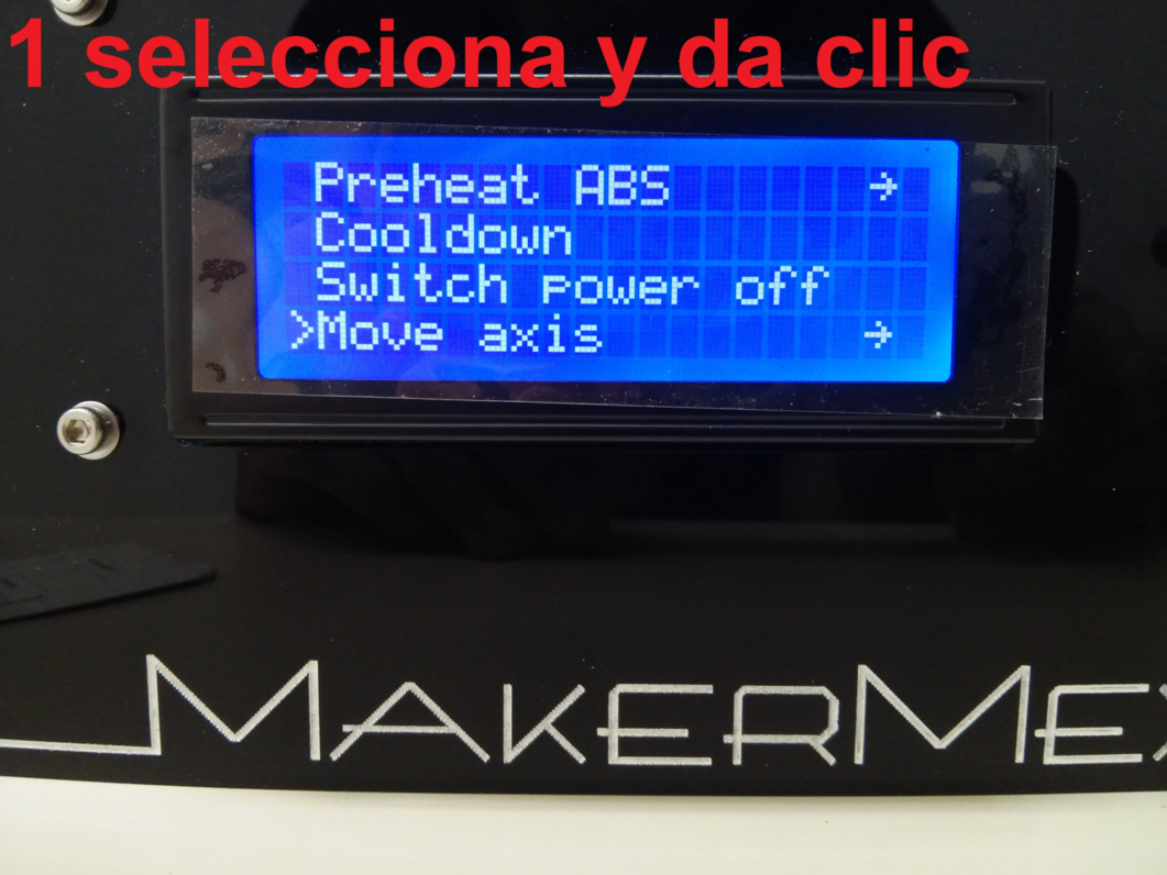
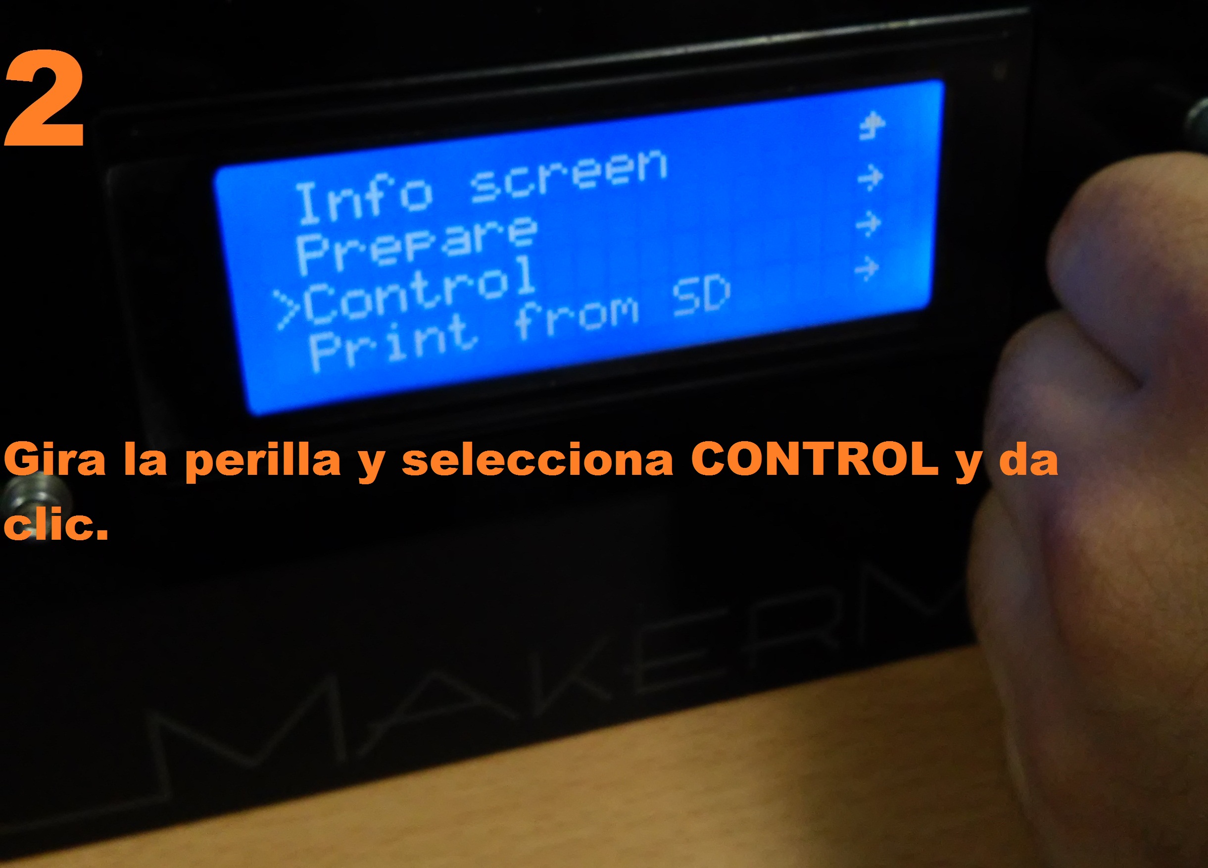
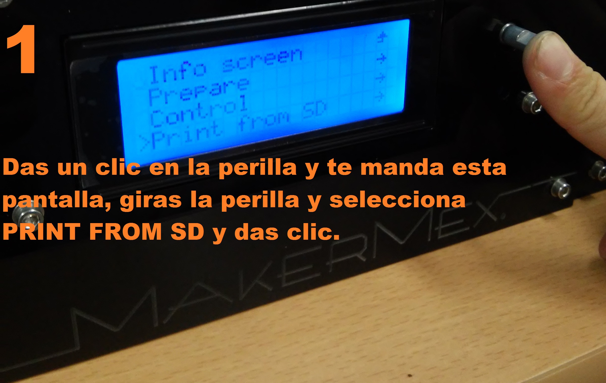
The main menu incudes:
| -PREPARE |
| -CONTROL |
| -PRINT FROM SD. |
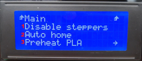
Turn the knob t select the PREPARE option, and then press t select it
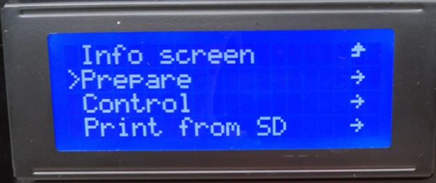
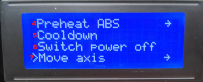
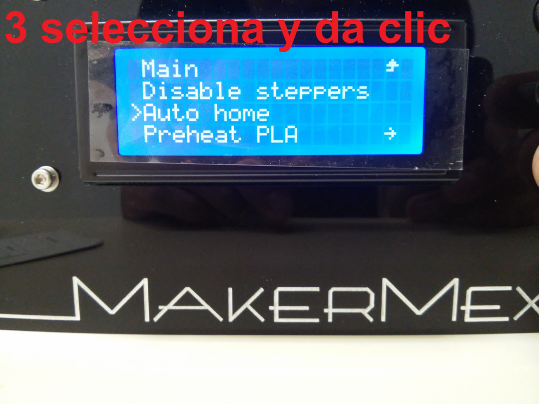
A new menu will appear, that includes:
| -Disable steppers |
| -Auto home |
| -Preheat PLA |
| -Preaheat ABS |
| -CoolDown |
| -Switch power off |
| -Move axis |
-Disable stepper
1.- It is used to unlock the motors, when you turn yur printer on, you can move the axis with your hands, but when you start printing or use the LCD control or the pronterface to move the axis you are not able to move them by handuntil yu use this option or turn of the printer.
-Auto Home
2.- With this option you will get the axis to the zero position (origin). After activting this option, X axis will move first to the right, then Y axis will move backwards and Z axis will move to top.
-Preheat PLA
3.- This option will heat up the nozzle and hot bed to the temperatures needed to print PLA, use it to change PLA filament or to prepare for printing
Preheat PLA has the following options:
| A.- Preheat PLA 1 2.-Preheat PLA 2 3.-Preheat PLA A11 4.-Preheat PLA bed |
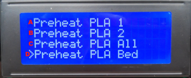
A.- activating it, start to heat the noozle 1 and the hotbed, B.- Activating it start to heat noozle two and the hotbed, C.- Activating it will start to heat the two noozles and hotbed, D.- Activating it will heat the bed
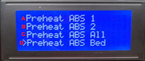
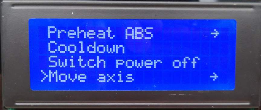
-Preaheat ABS
4.- Tis option will heat the noozle and hotbed with the temperature needed to print the ABS, yu can use it to change the ABS filament or to prepare for printing.
| Preheat ABS |
| -Preheat ABS 1 |
| -Preheat ABS 2 |
| -Preheat ABS A11 |
| -Preheat ABS Bed |
-Cooldown
5.- This option will deactivate or cancel the heating of noozle and bed.
-Switch power off
6.- This option es acts as an emergency stop, we prefer to use the power source
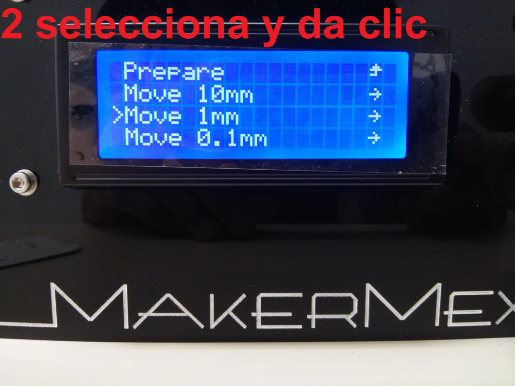
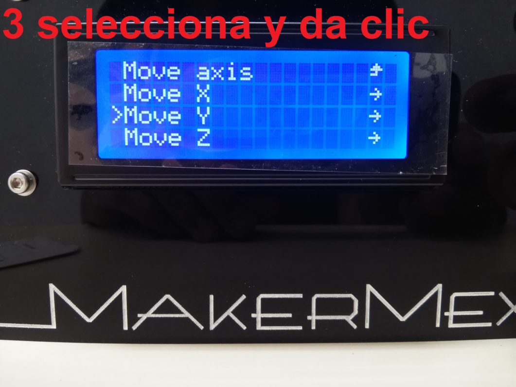
-Move axis
7.- This option allows to ineract with the ais, it means that we ca move them t diferent velocities to calibrate the bed.

Clickin on the “Move Axis” option will show the following screen, where we can select the distance that we want to move turning the knob, we have 3 option:
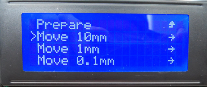
When we select 10mm we can only move the X or Y axis, when we select 1mm option or 0.1mm we will be able to move every axis or the extruder.
After you select the distance, you can se a new screen with options.
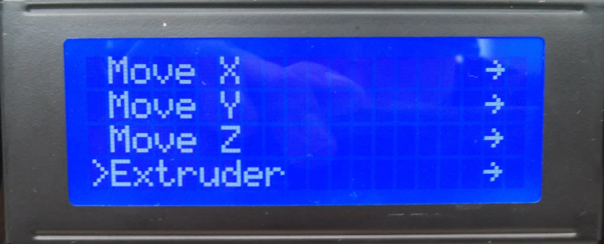
After selecting the desired option it will show the 3 axis.
X axis
Y axis
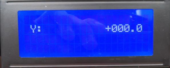
Z axis
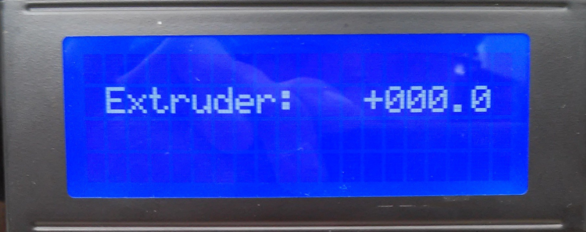
Extruder
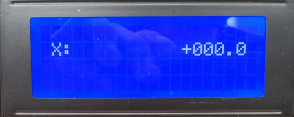
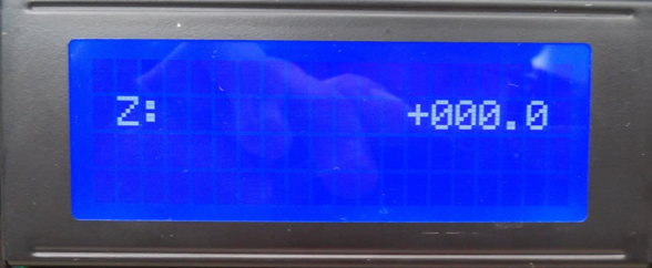
Note
You can turn the knob clockwise or counterclock to move the axis to the positive or to the negative.
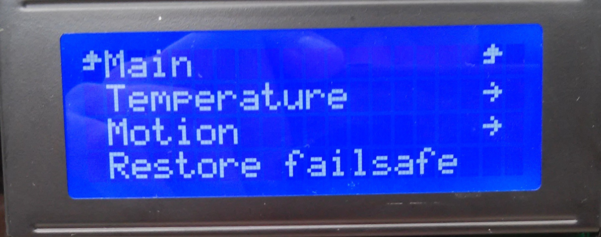
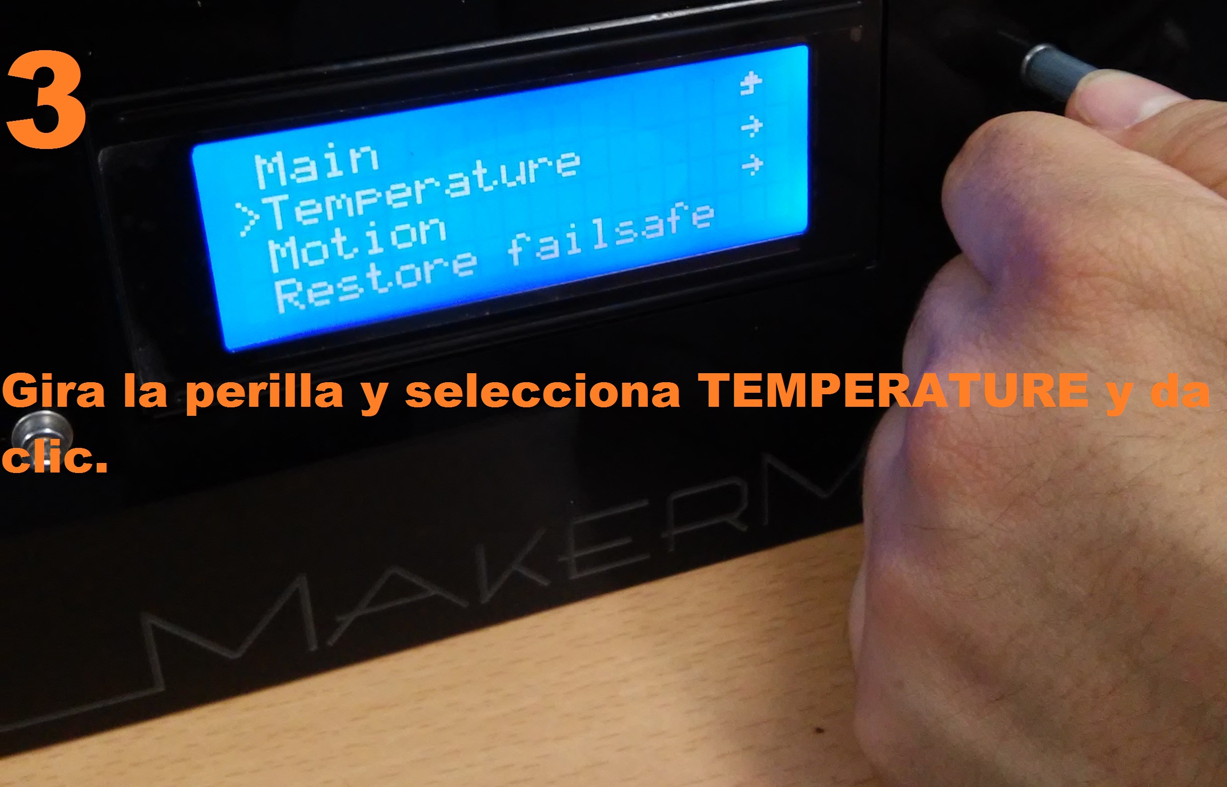
The CONTROL menu contains the following options:
| Temperature |
| -Motion |
| -Restore failsafe |
Usually we only need the TEMPERATURE option
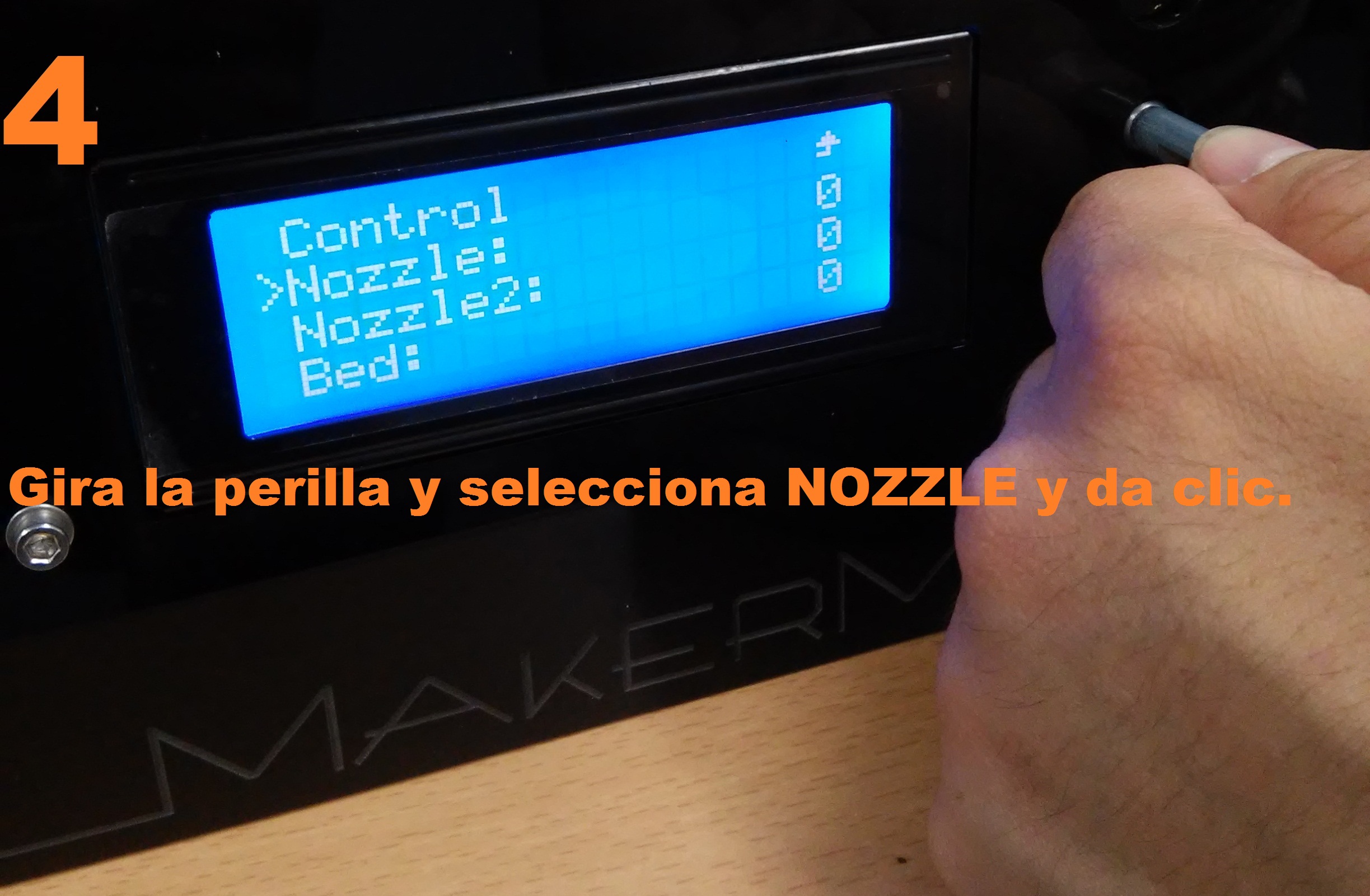
The TEMPERATURE menu has the following options
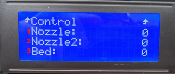
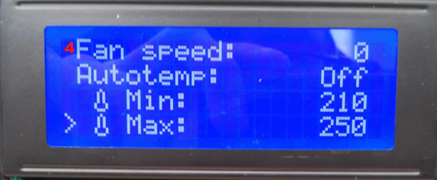
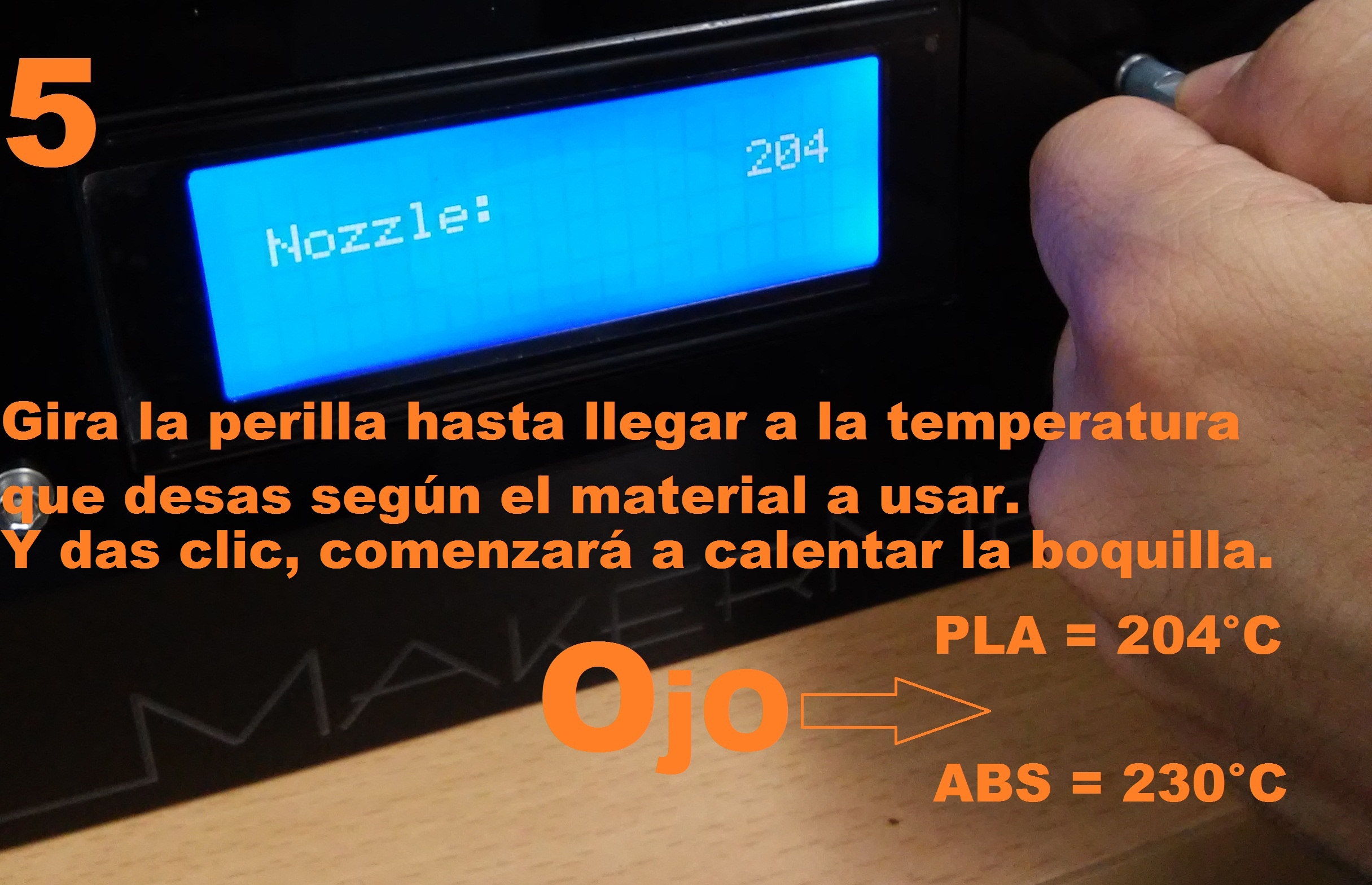
1.- Click to activate it, then turn the knob to apply a temerature to noozle 1, click again.
2.- Click to activate it, then turn the knob to apply a temerature to noozle 2, click again.
3.- Click to activate it, then turn the knob to apply a temerature to the hotbed, click again.
4.- Click to activate it, then turn the knob to apply a temerature to noozle 1, click again.
Note
The LCD screen is the controller for the print, is very important to use only the options detailed in this manual
The PRINT from SD option allows to select a G code from the SD card to print
TIPS FOR SSCREEN USAGE
- Remember that the knob is multifunctional, it allows us to select and activate each option on the screen.
- While the machine prints we can use some options, like turn up nd down the temperture of the noozles or the bed, or speed up and down the cooling fan
- With the screen we can also modify the printng speed, to do this simply turn the knob while printing, if you click clockwise the speed will increase, if you turn counterclock it will decrease.
- You can find the printing speed in the screen as a porcentage, 100% means that we are printing at the speed configured in cura (usually 50 mm/s).
Example
| Speed |
| 50mm/s = 100% 100mm/s = 200% 150mm/s = 300% |
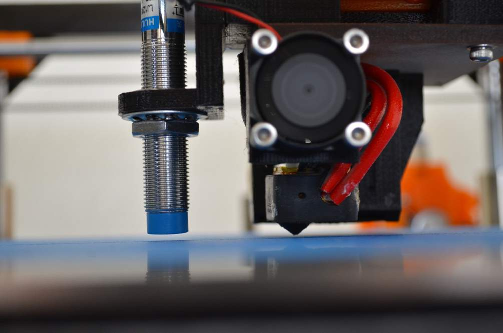
Printer calibration (distance between the noozle and the hotbed)
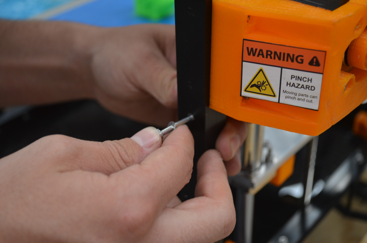
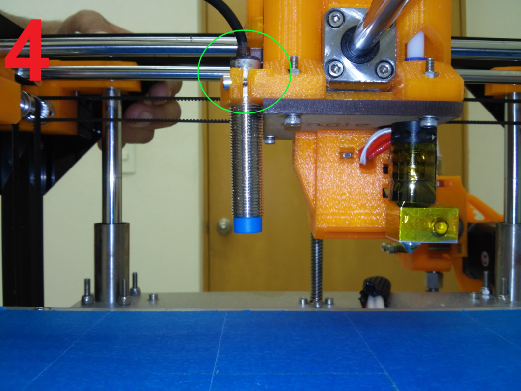
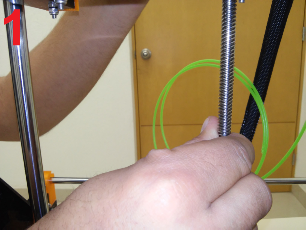
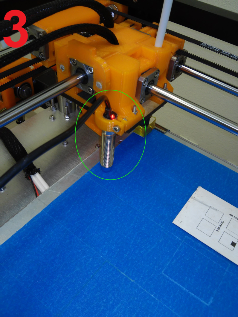
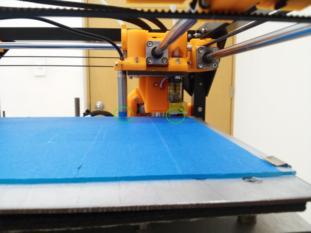
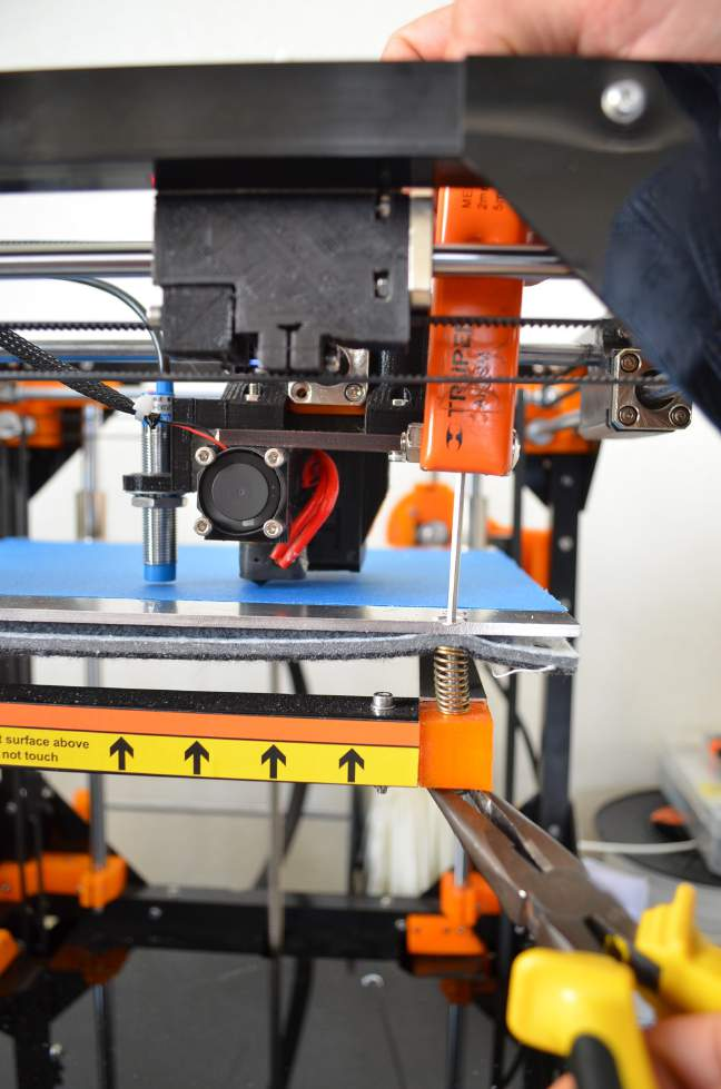
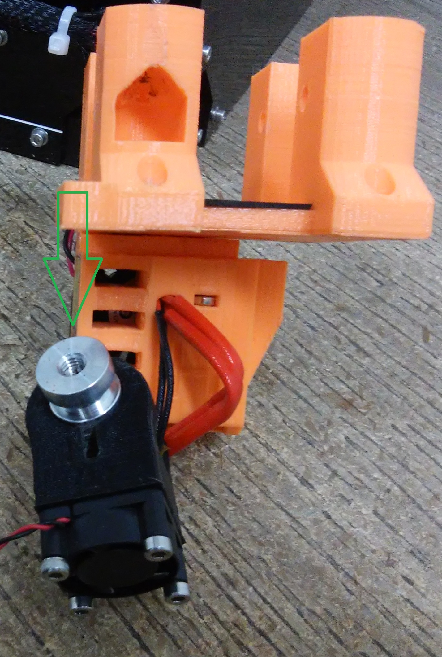
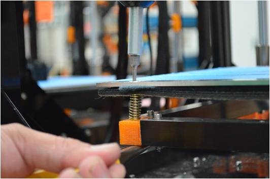
Step 1
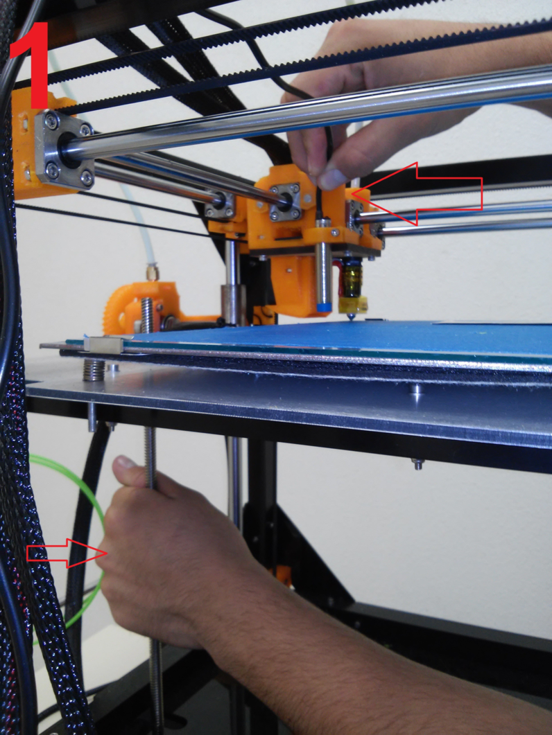
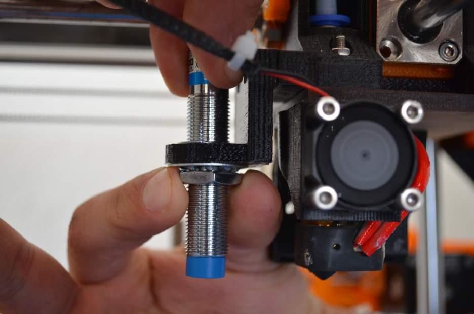
unscrew the inductive sensor with an 2.5mm allen wrench and move it upwards as shown in the image
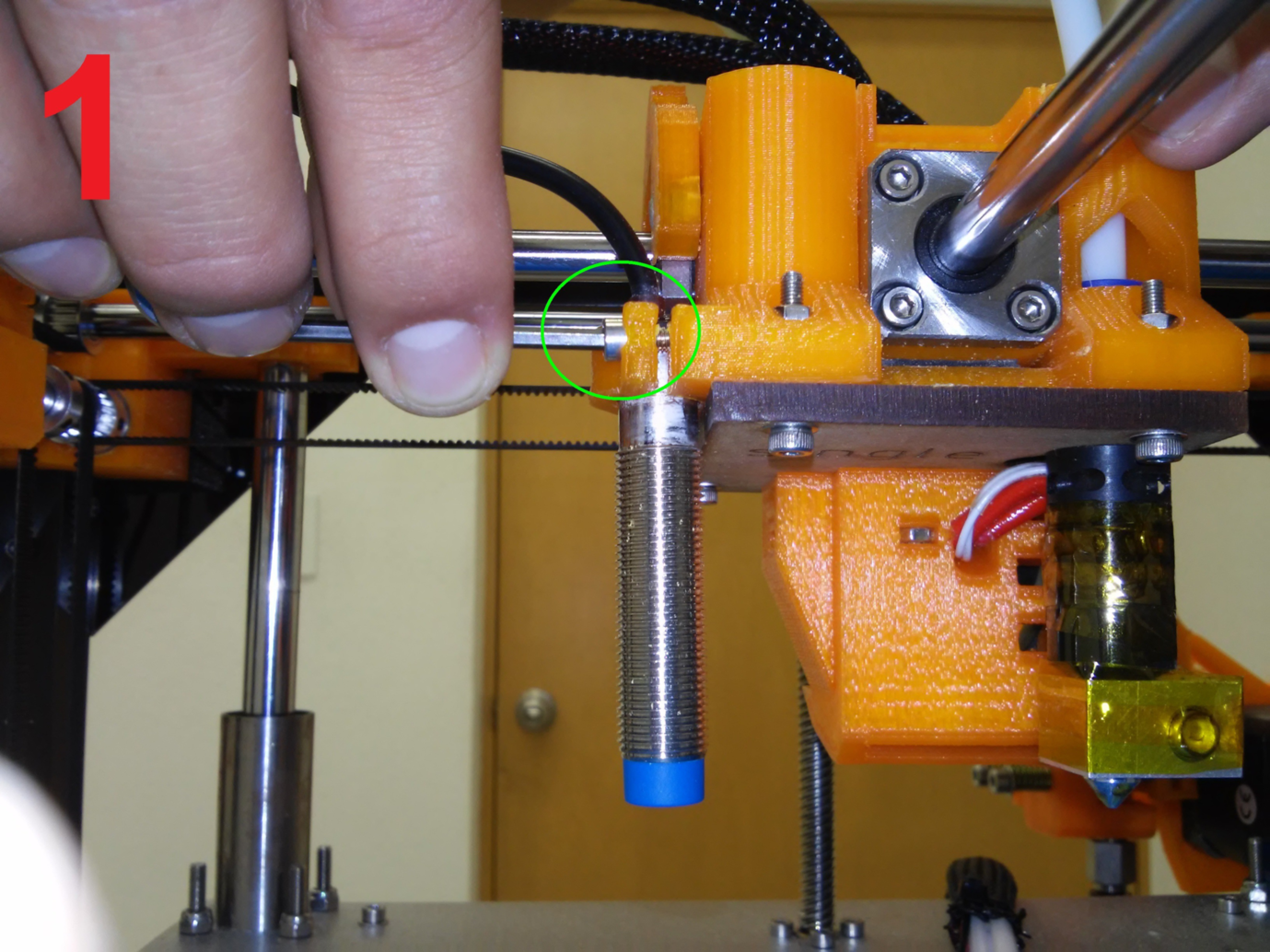
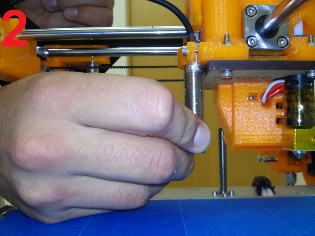
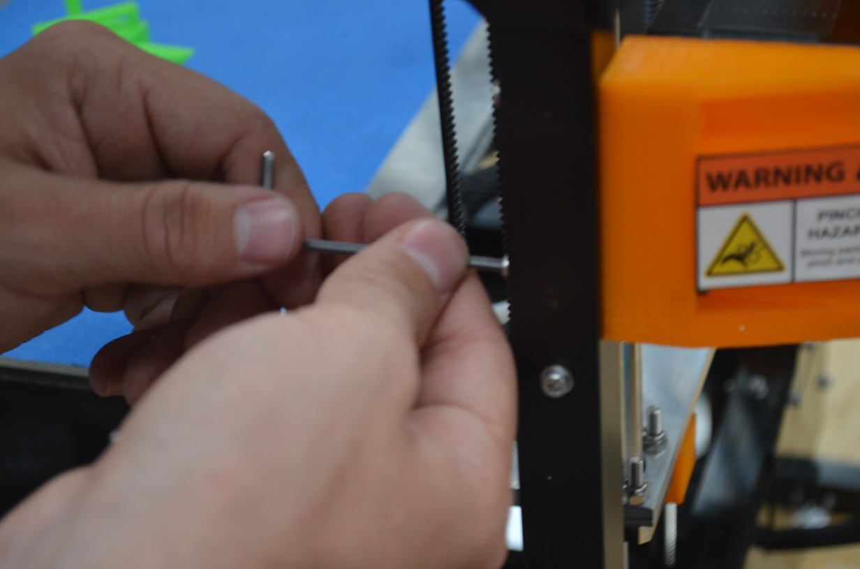
Step 2
turn gently the Z axis so it moves upward, we need that the distance between the noozle and the hotbed is equivalent to the thickness of a business card
Note
The business card need to touch gently the bed and the noozle to ensure the distance is correct
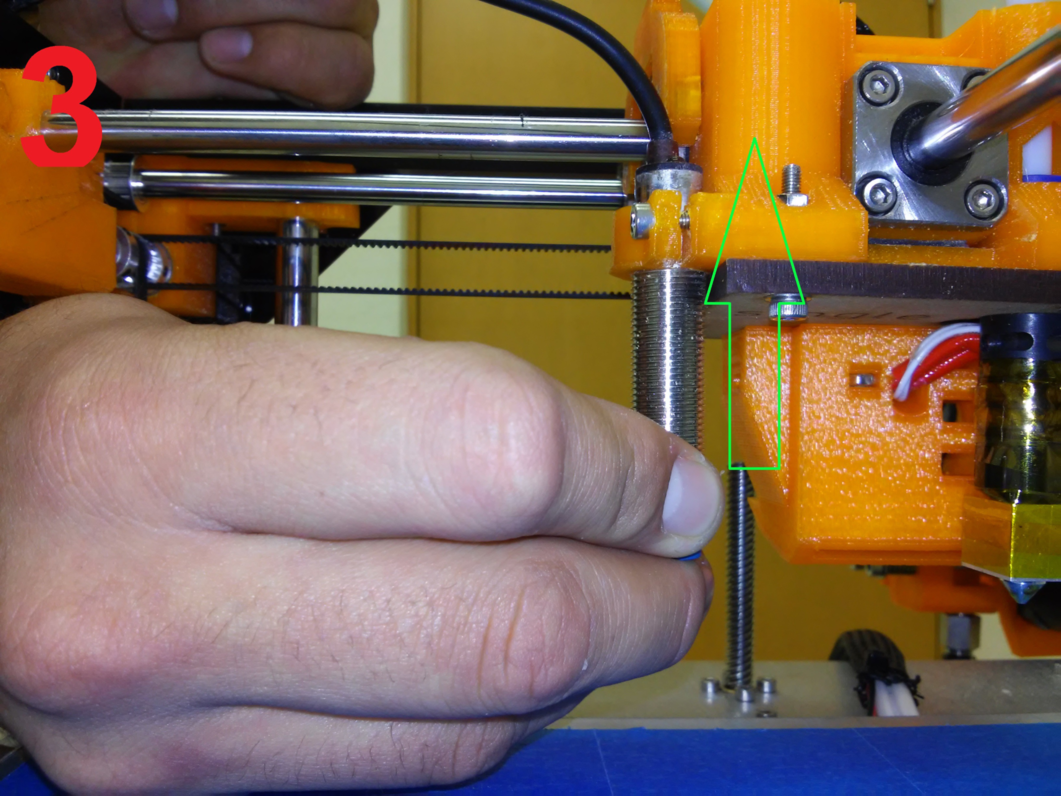
Step 3
Once we made sure the distance between the noozle and the bed is correct we wil adjust the inductive sensor very carefully to ensure the Z axis doesn’t move downwards.
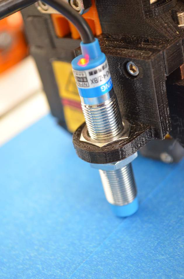
We need to djust the sensor to the detection point.
1.- Turn the power source on, 2.-Hold the Z axis to mantain the distance. 3.- Move the sensor until the LED is activated in red. 4.- Screw with a 2.5mm Allen wrench or with a chain nose jaw plier to hold firmly, make sure the LED is on.
Note
The most important thing is to get the inductive sensor in the correct position, it s just when the led turns on.
Step 4
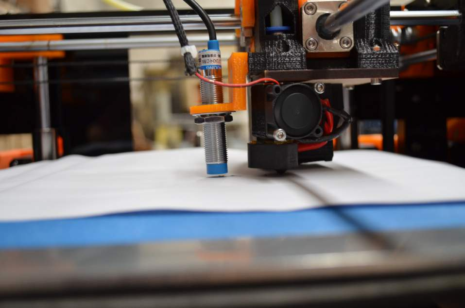
As an aditional test we will select the “autohome” option in the screen to ensure the calibration went fine.
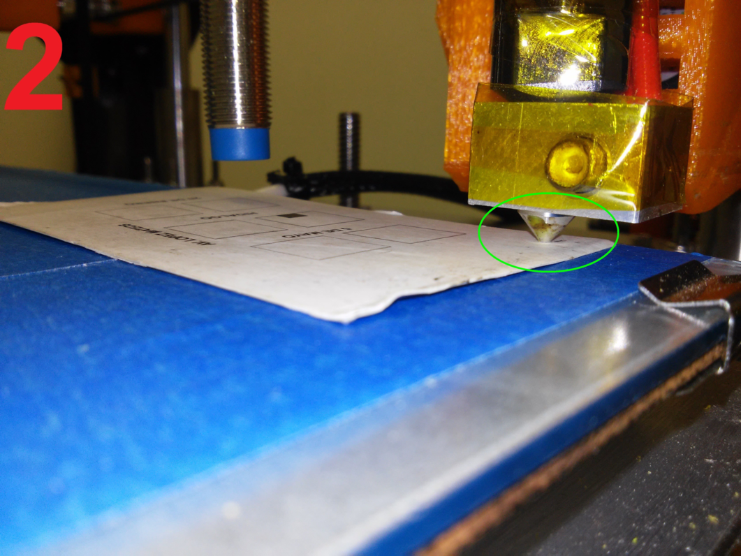
Once in home (0,0,0) position you can see a very small distance between noozle and bed.
Step 5
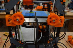
Now we will move the X, and Y axis using the screen.
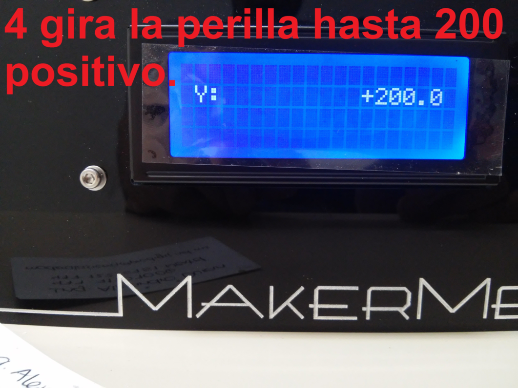
Lets start moving the Y axis to ensure the bed is calibrated in its four corners.
Always use the business card to compare the correct distance.
If the LED of he sensor does not turn on, we will need to adjust the springs of the bed using a 2.5mm allen wrench and a chain nose jaw plier to adjust the nut.
If the distance in a corner is bigger than the correct we have to unscrew, if the distance is to short we have to screw.
Note
If Z axis moves down you can select autohome again to continue calibrating.
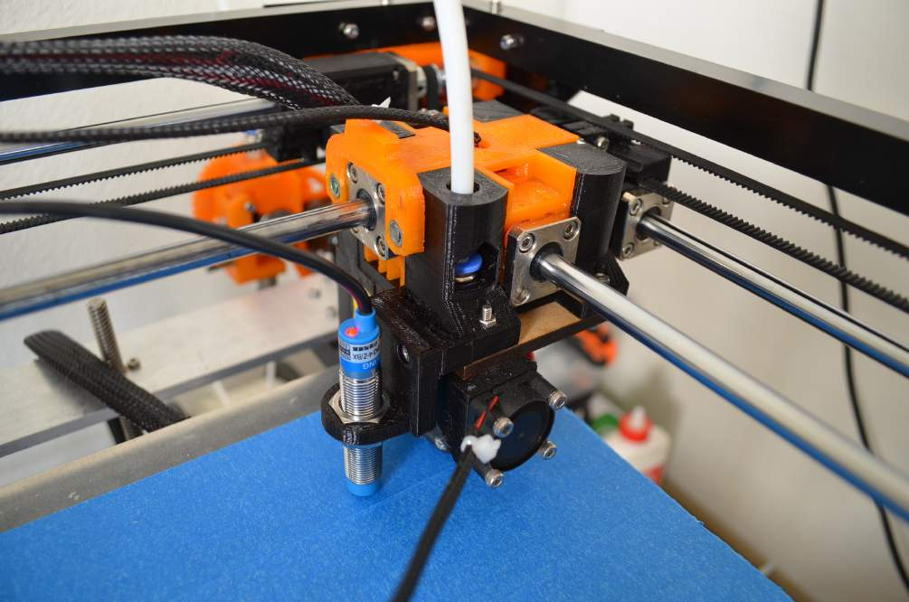
Printer Calibration (noozle-bed distance) MM1 V1.5
Step 1
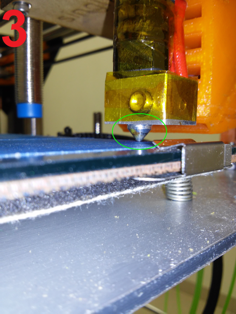
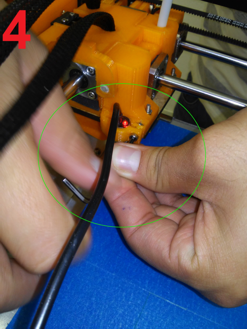
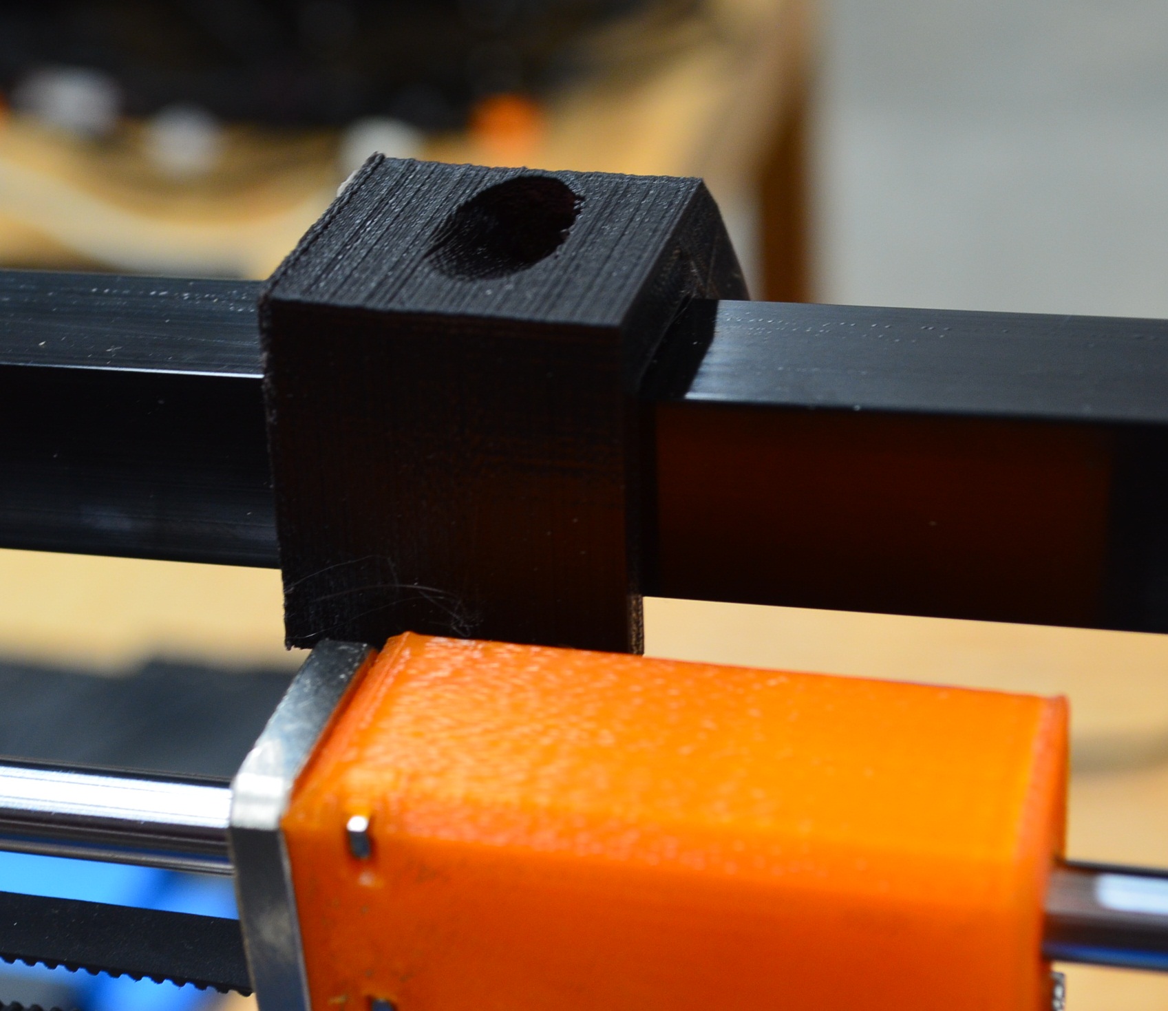
Identify the Z sensor, on the top it has a LED that turns on when detects the hotbed, in the bottom part it has a nut that you can unscrew to release the sensor to adjust the distance.
once we have identified the sensor we will go to autohome using the screen (X0,Y0,Z0) then we can manually move z axis up or down as needed to get the distance of the thicknes of a business card or a similar object between the noozle and the bed.
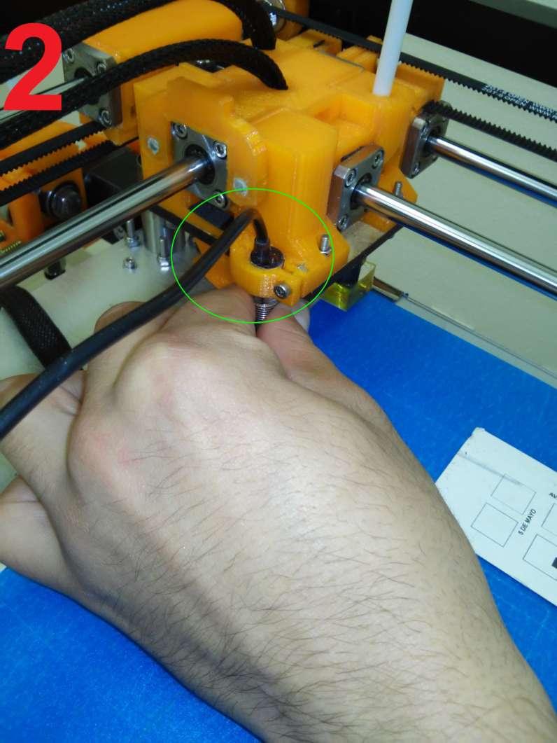
now we unscrew the nut of the sensor to move it up or down as needed to make the LED turn ON
Once the LED is on, we adjust the nut, and the calibration is ready. Next we will check the four corners of the bed to see if it is well leveled.
To calibrate the four corners of the bed we have to use the “Move axis” option to move on X and Y separately.
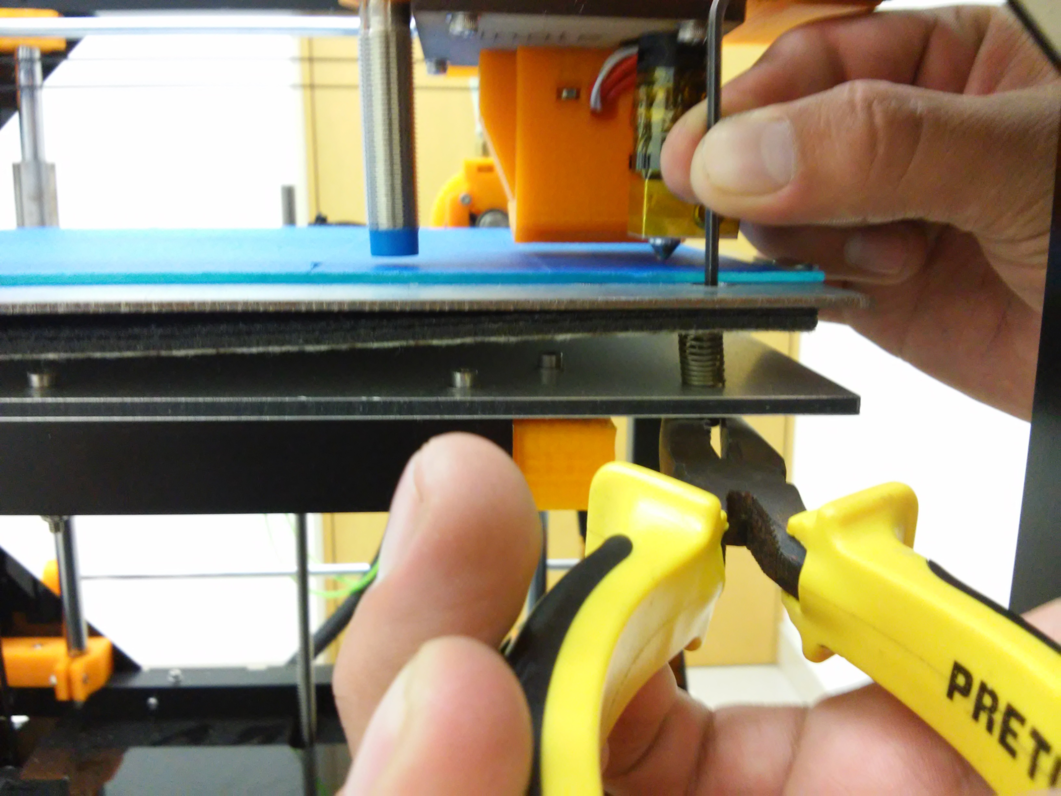
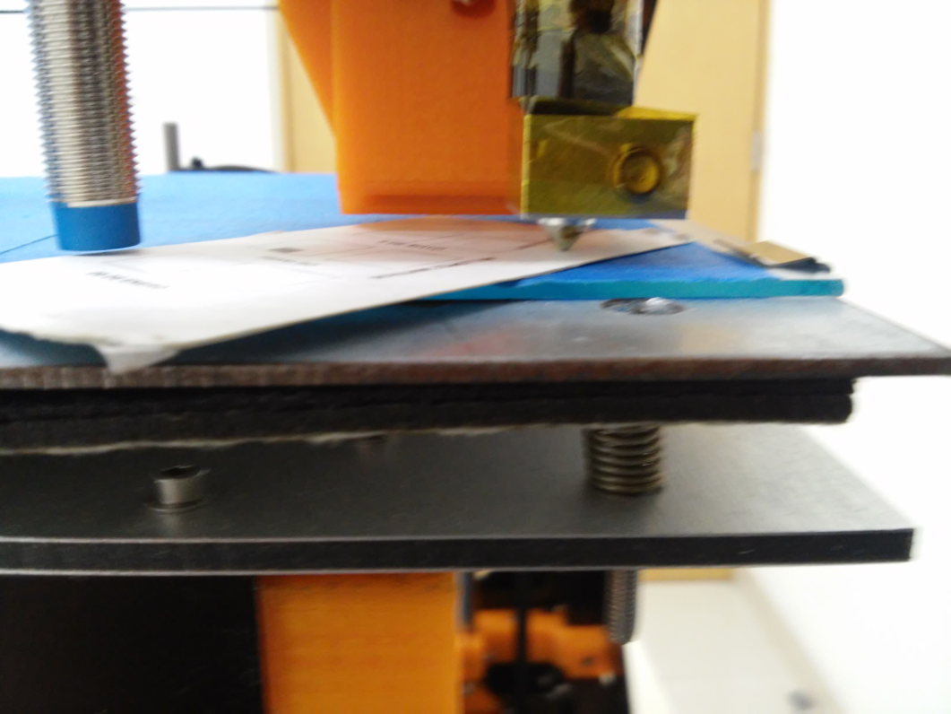
First we will move the Y axis to the position shown in the image, if the LED turns off it means that the bed is not being detected, we have to move that corner upwards until the led turns on, if the LED is on but the noozle touches the bed we have to move down that corner of the bed to give more distance. The distance must be the same on each corner.
To move the bed up or down you can use a chain nose jaw plier and a M3 allen wrench, holding the nut with the pliers and screwing with the wrench
Repeat the steps on the X axis.
Repeat to the other side
Ready, you have your bed clibrated to print your designs!
You hav already unpacked your 3D printer, now, lets make it to print!
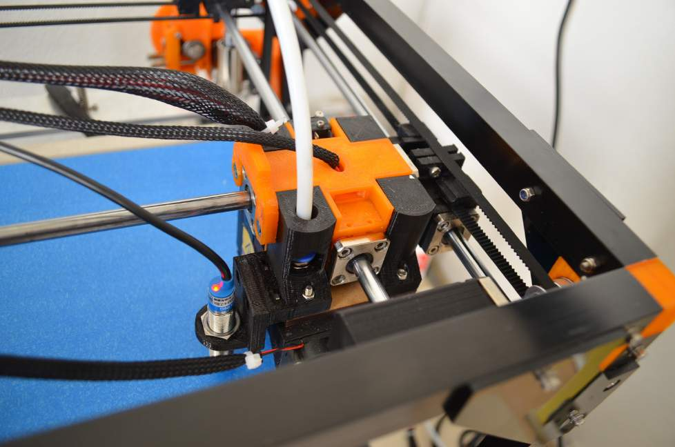
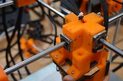
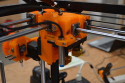
Step 1
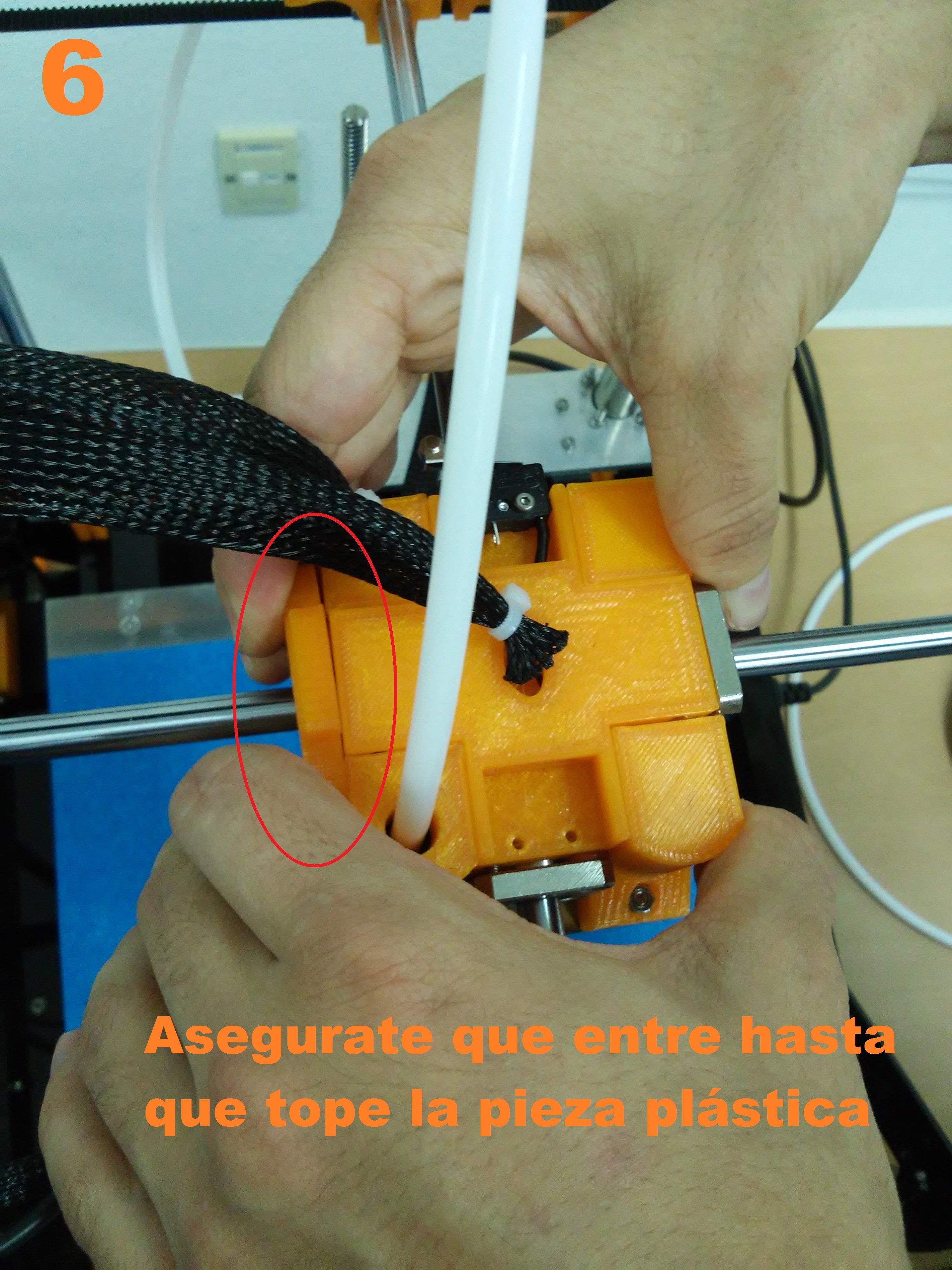
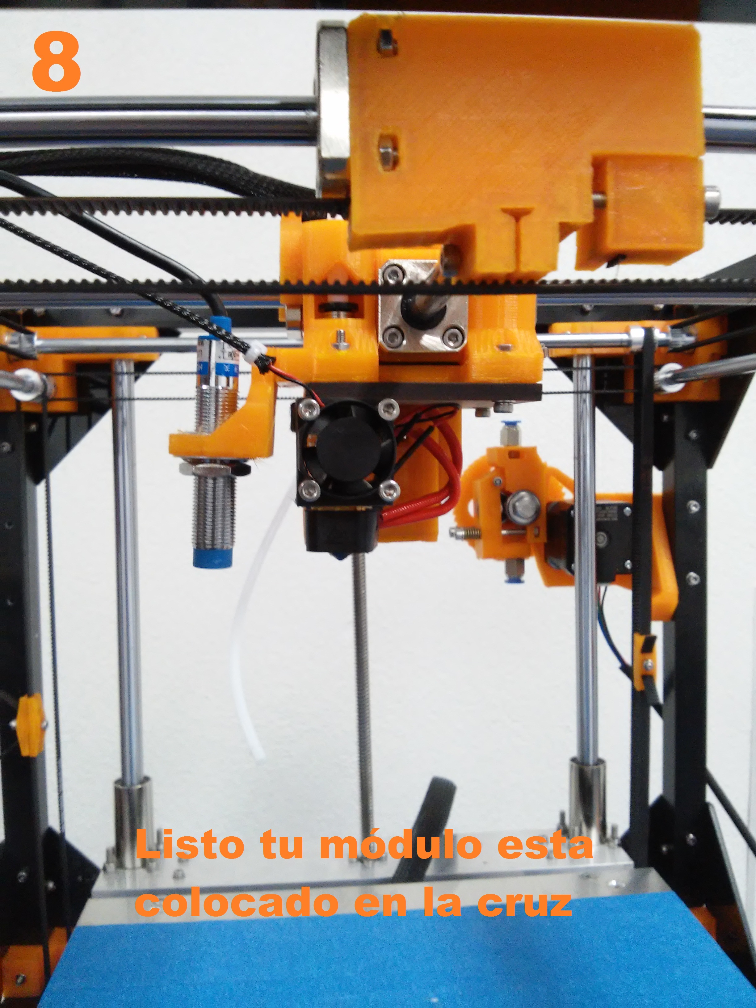
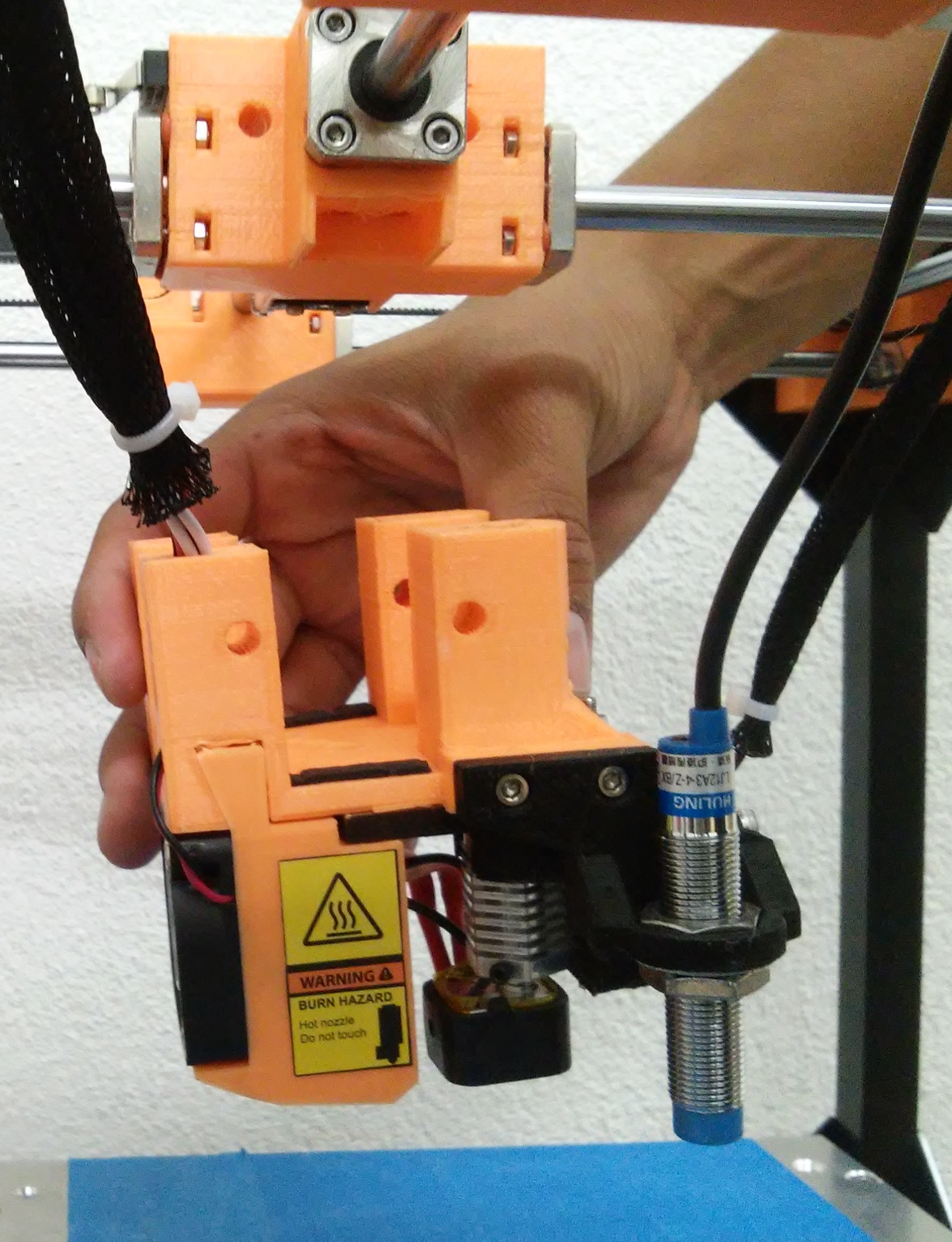
On this part of the manual we will install the printing module if is not already installed; the module is the part where the noozle is, t must be installed in the cross, then you have to put the clip and conect the wires.
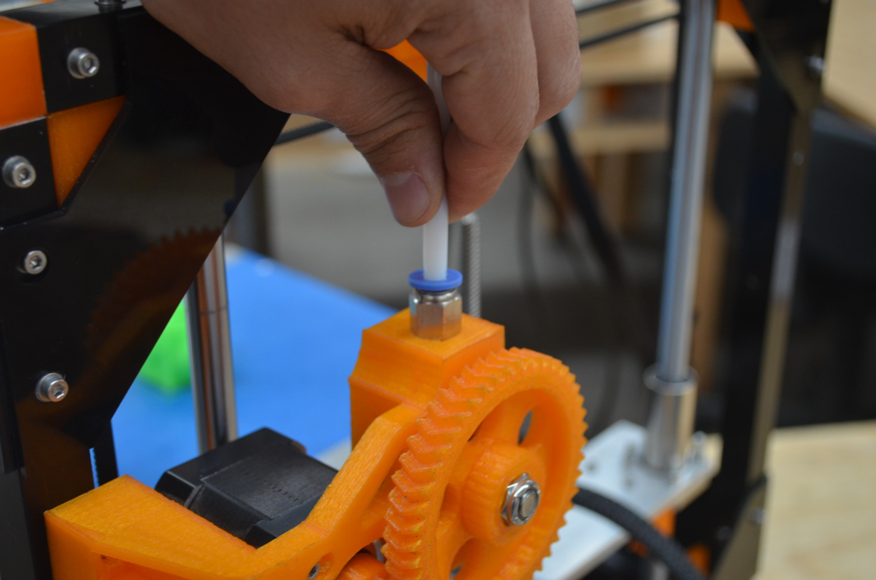
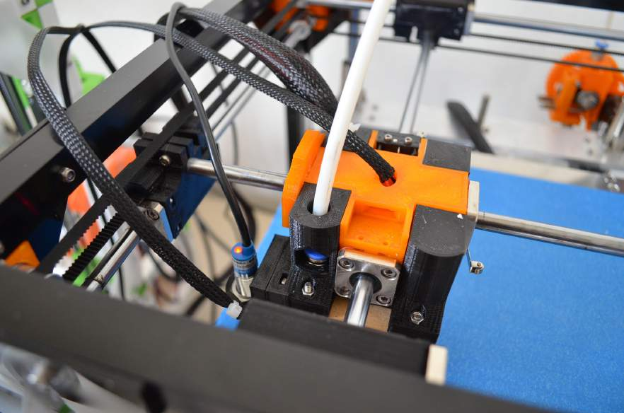
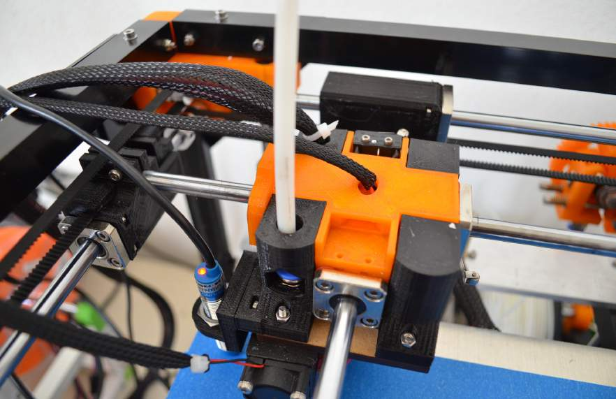
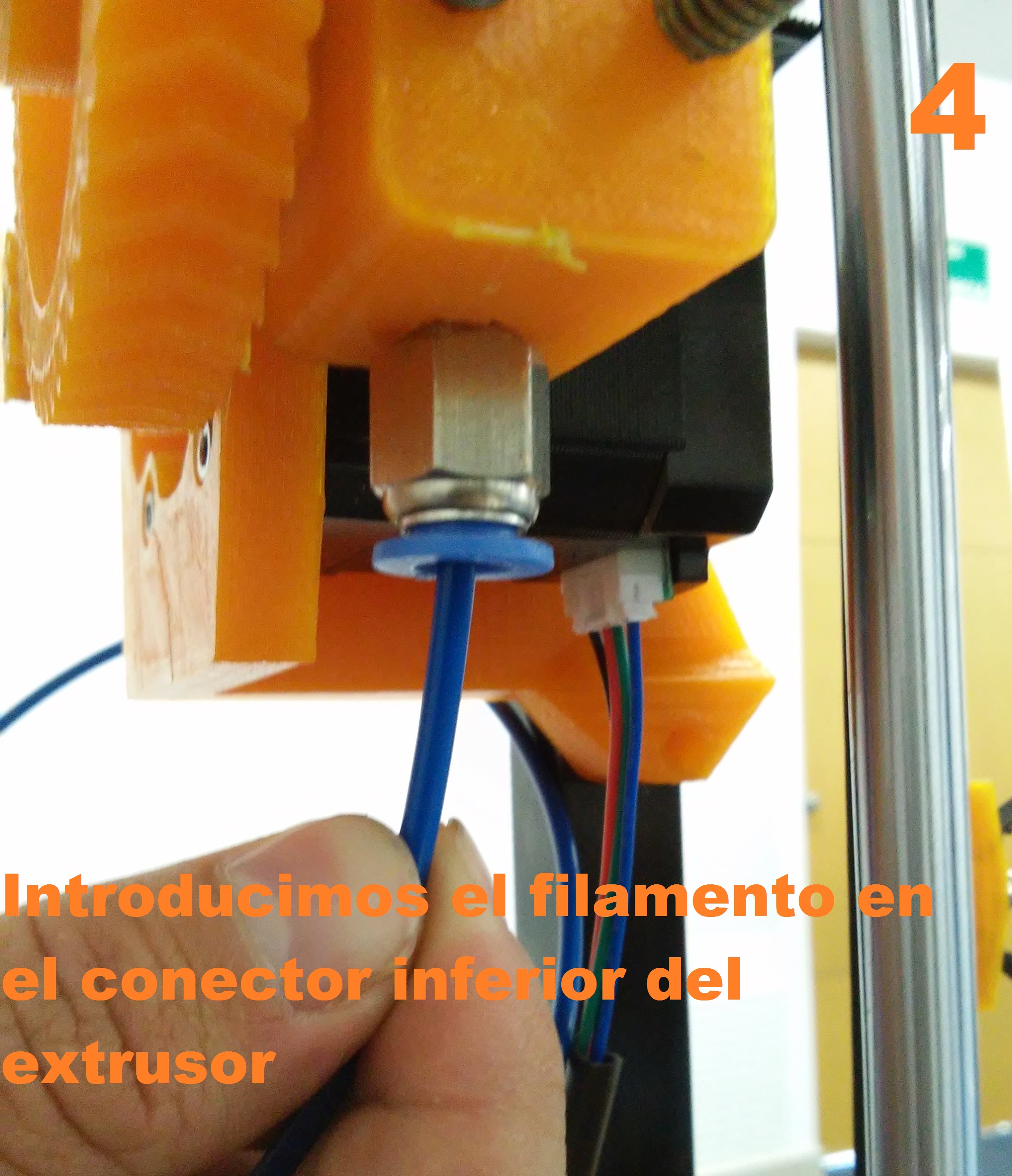
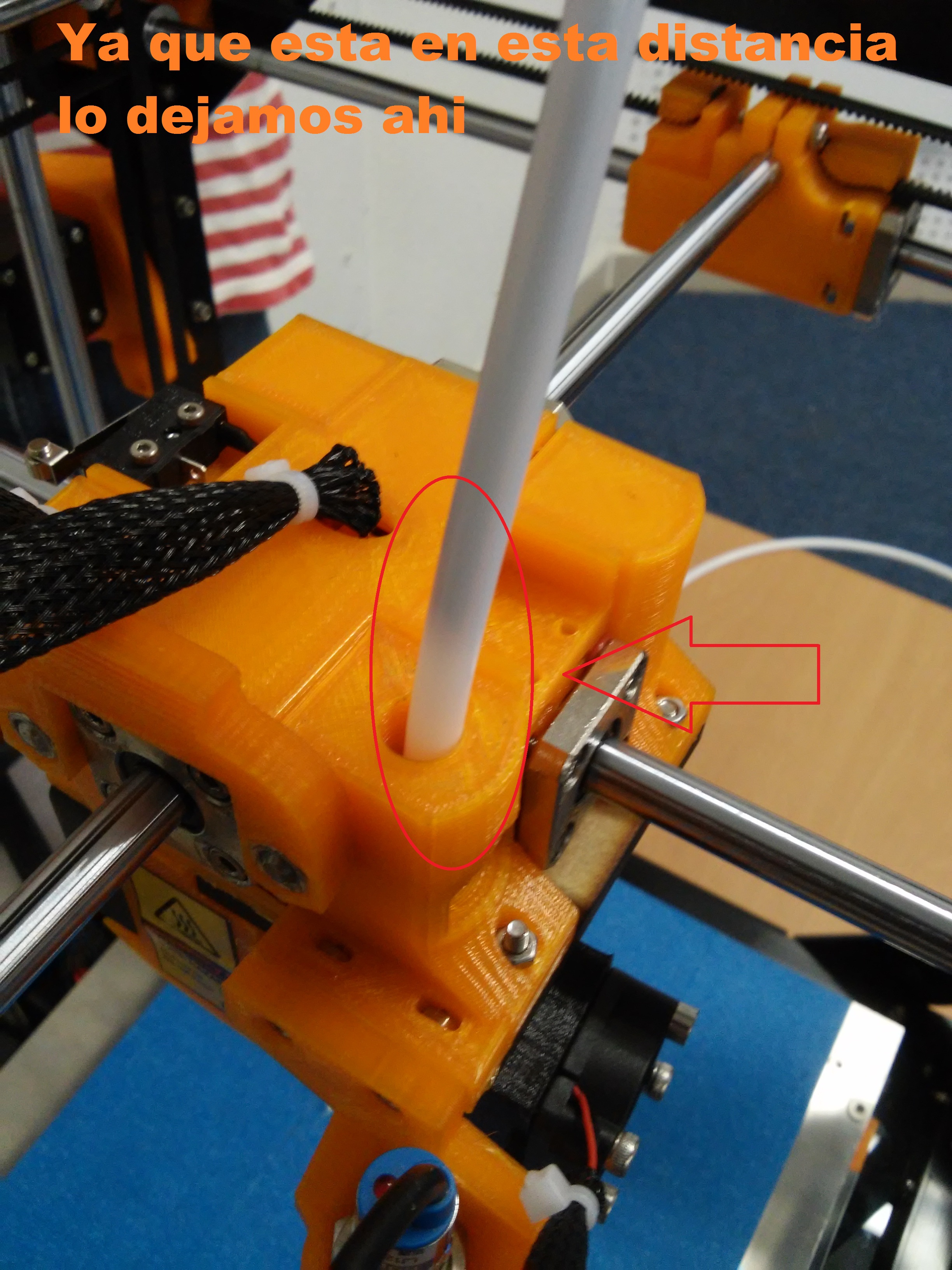
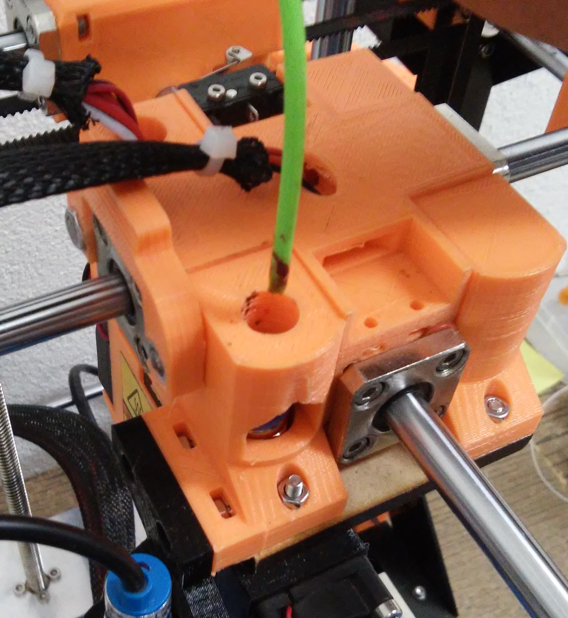
Step 2
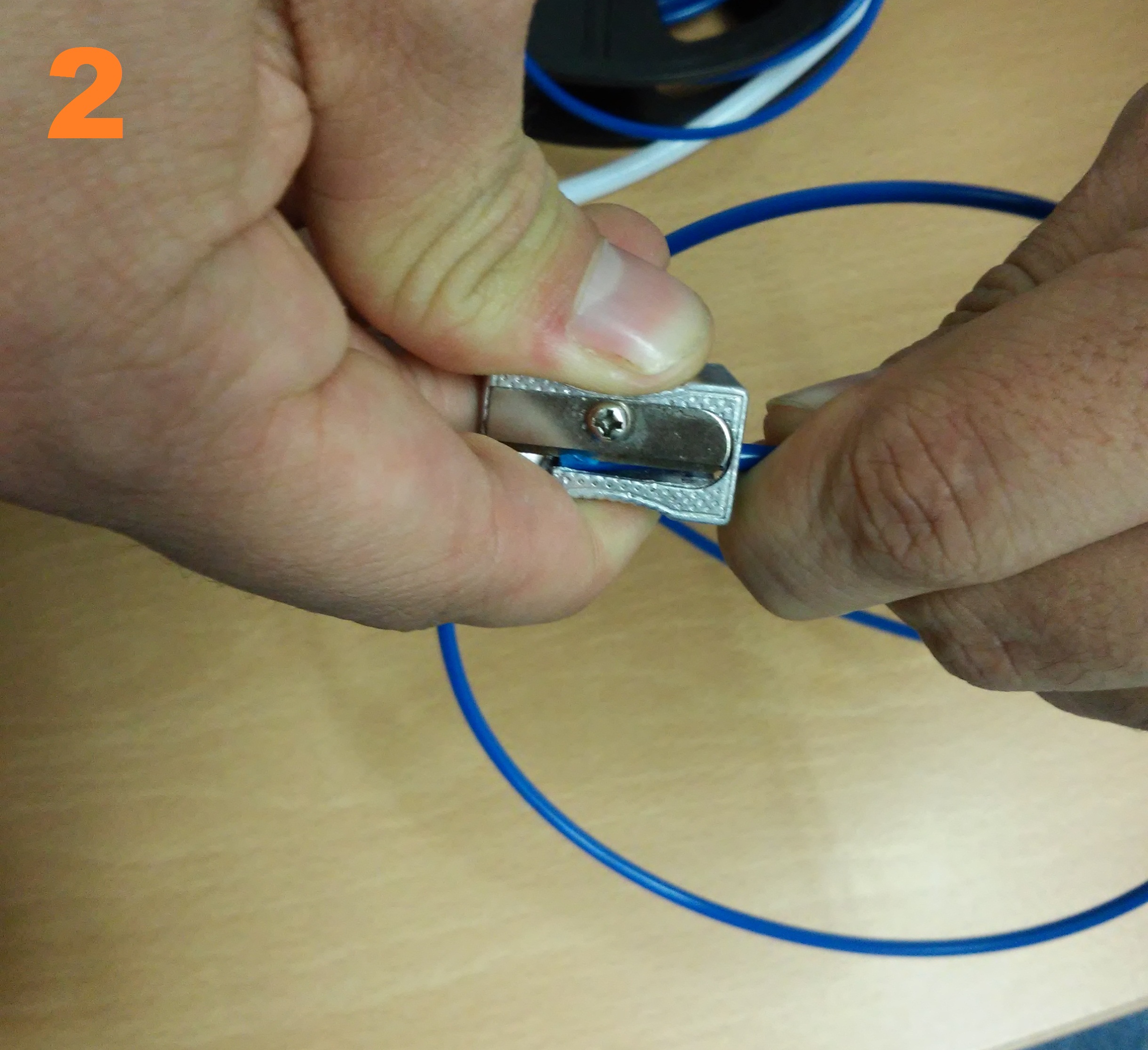
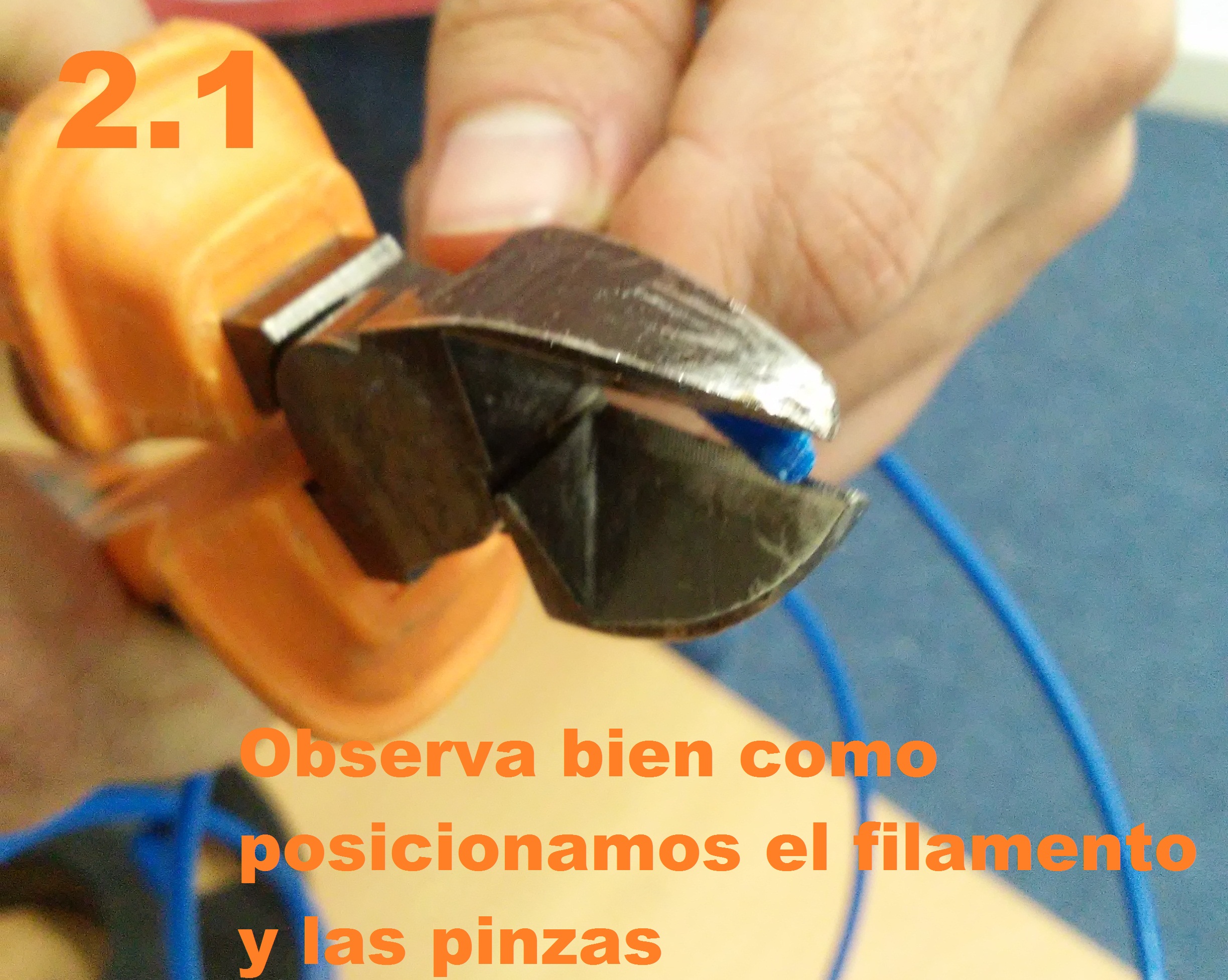
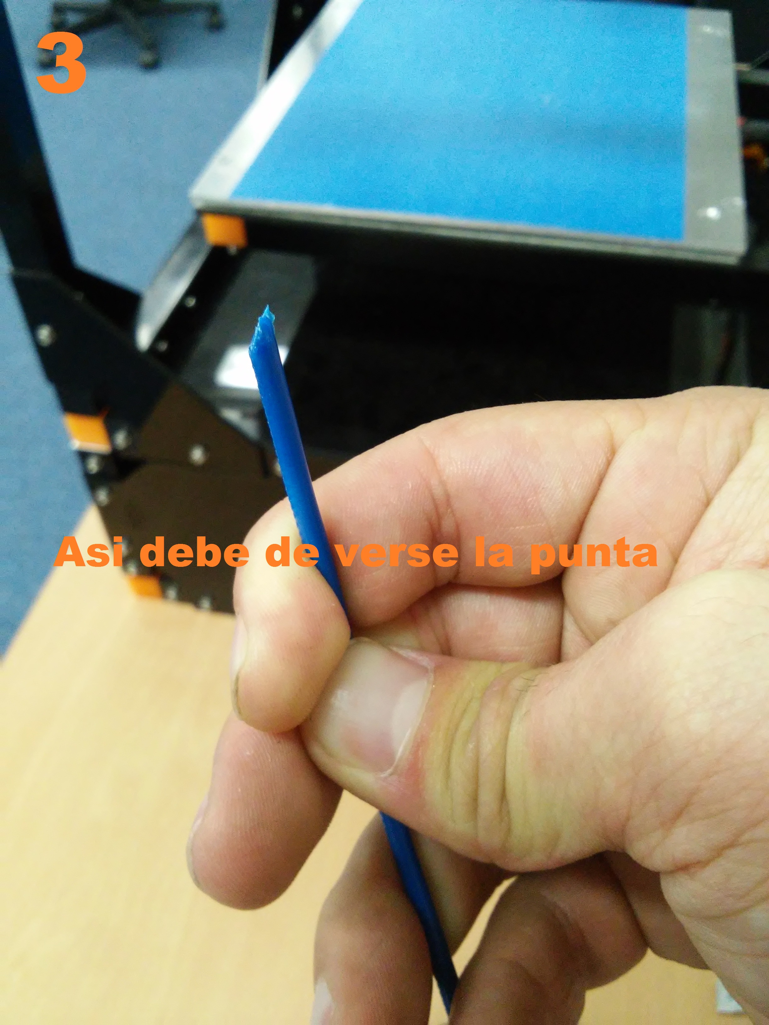
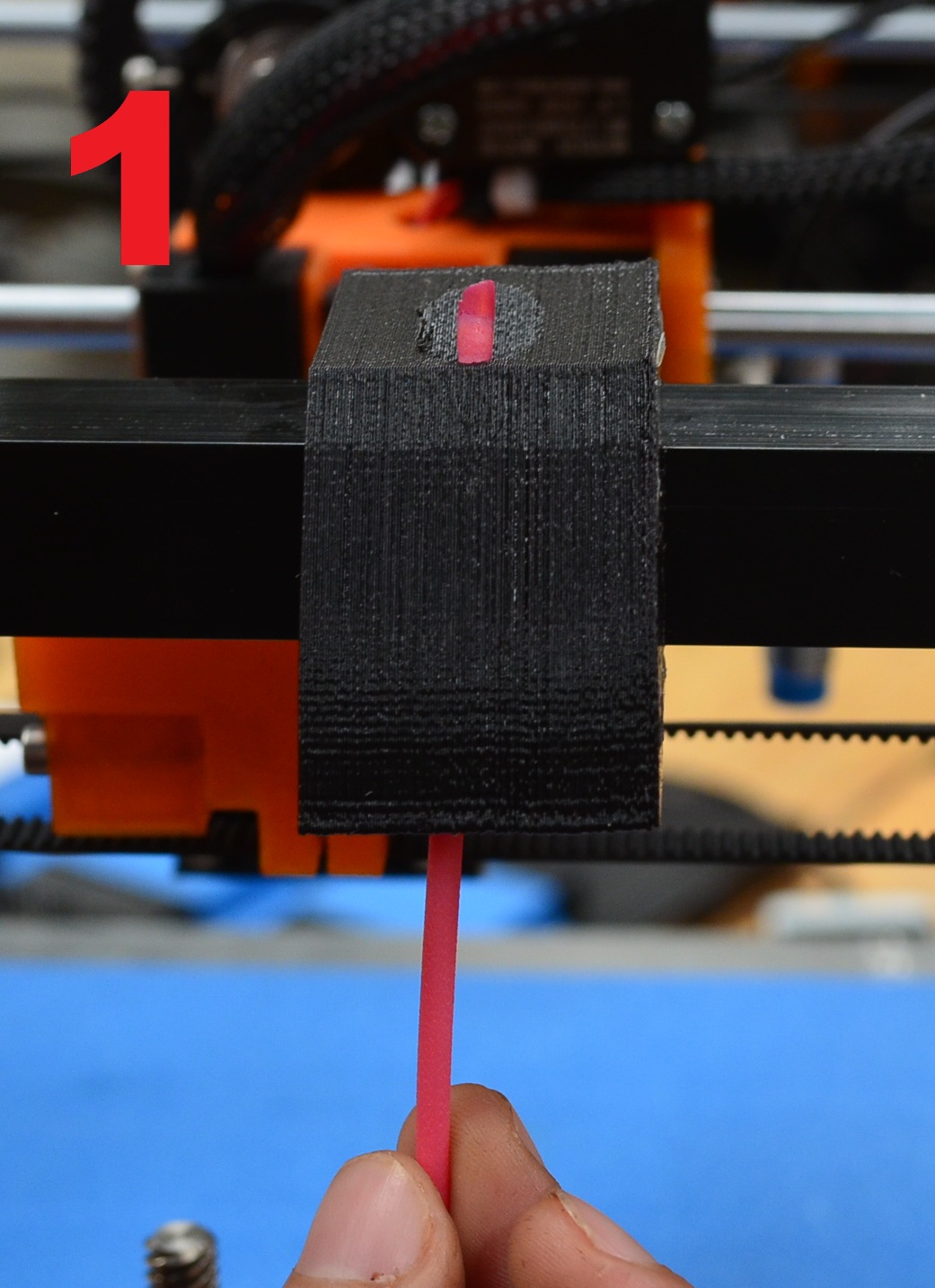
Now, we have to connect the bowden tube (the white tube) in the blue connector, now we need to sharp the filament to get it into the noozle.
Note
The sharp we got in the filment will guide it throug the noozle, we can sharpe it using a pencil sharpener or jaw pliers.
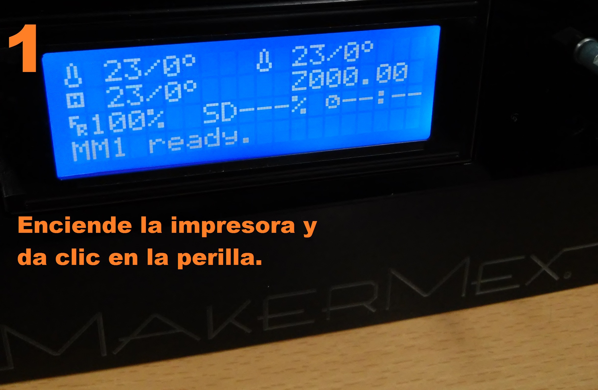
Step 3
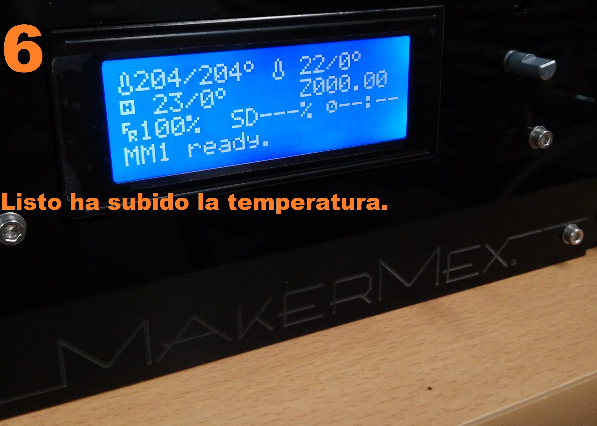
Turn on the printer, heat the noozle to 204°C for PLA or 230°C for ABS
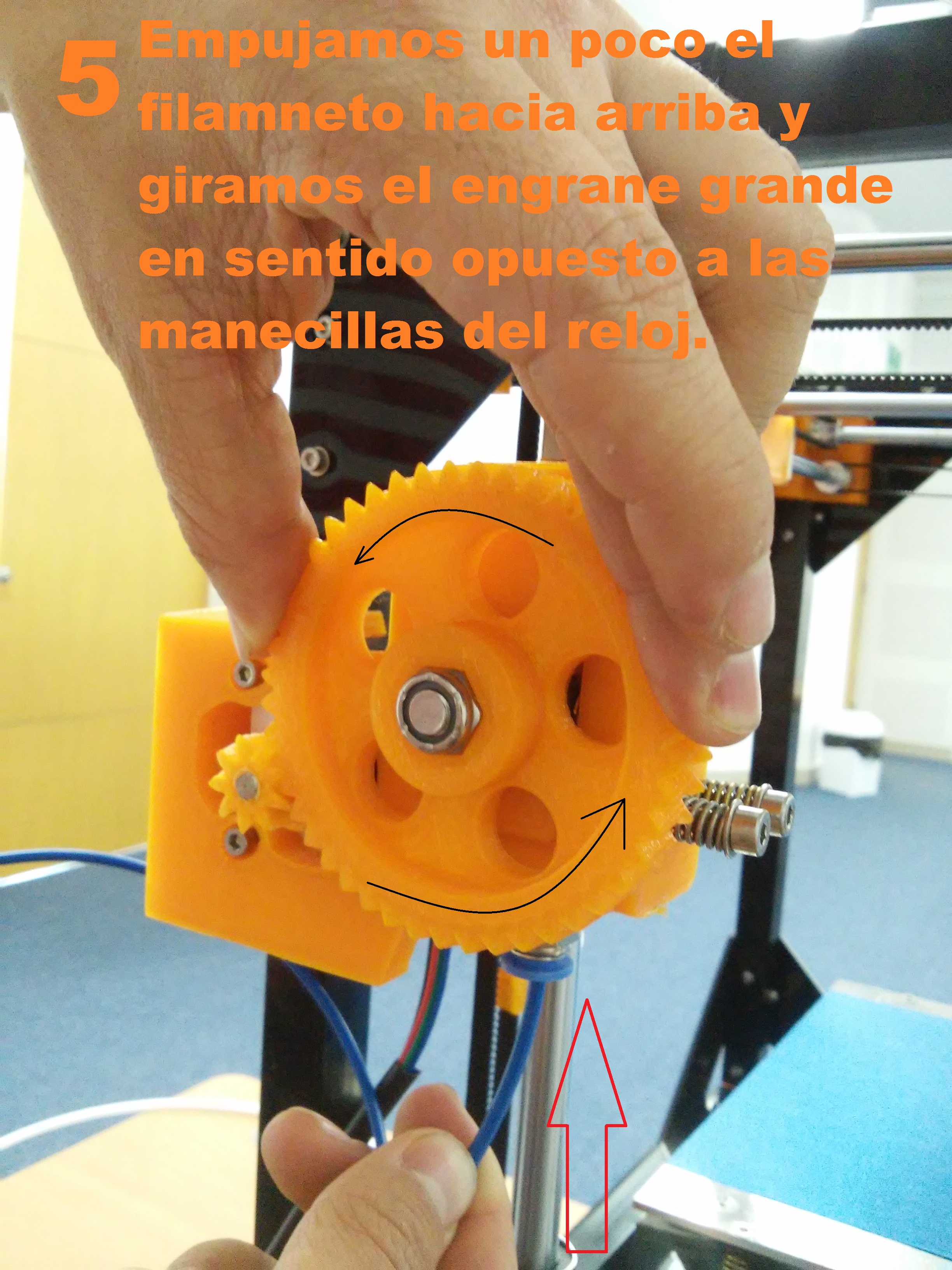
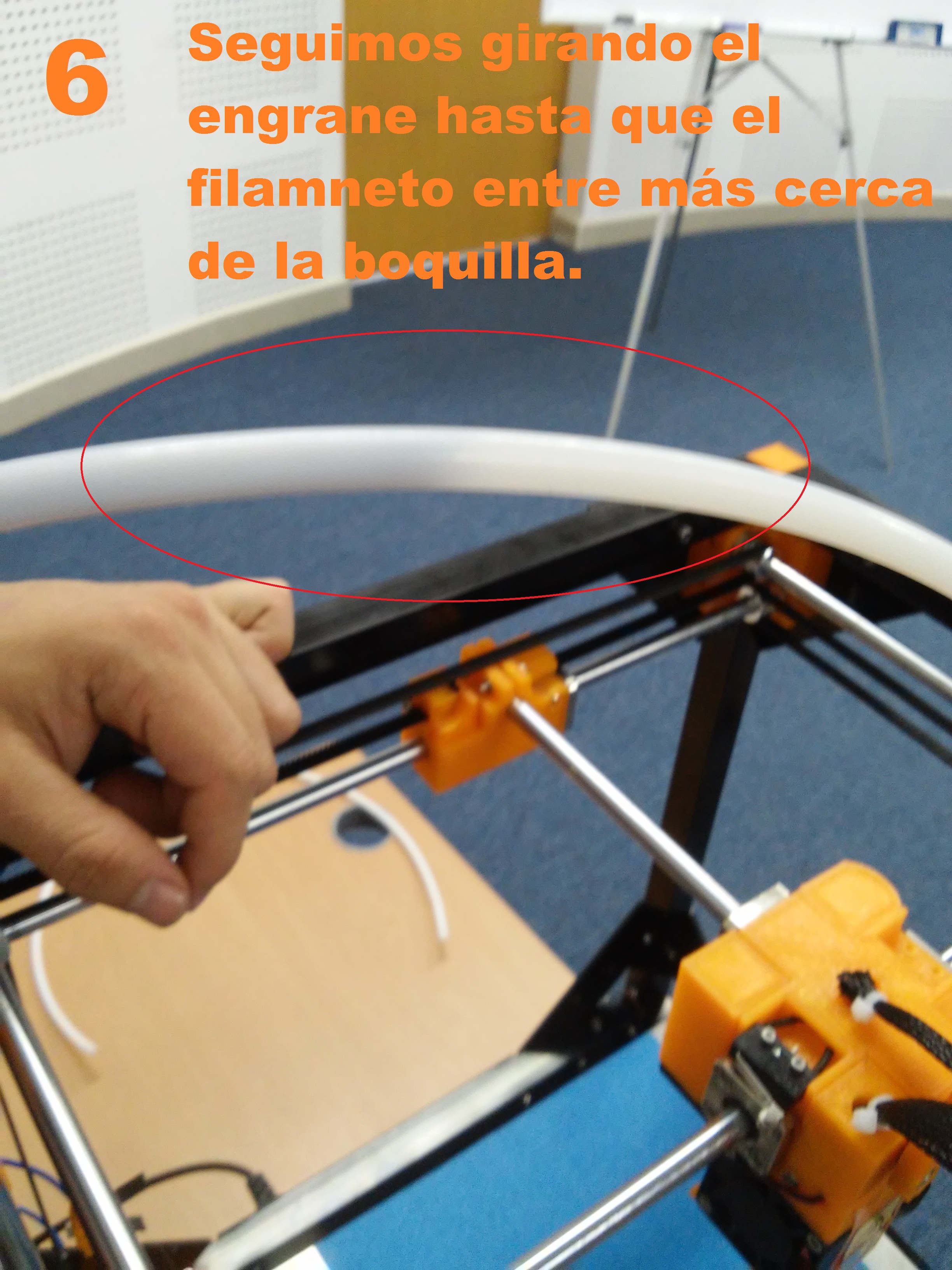
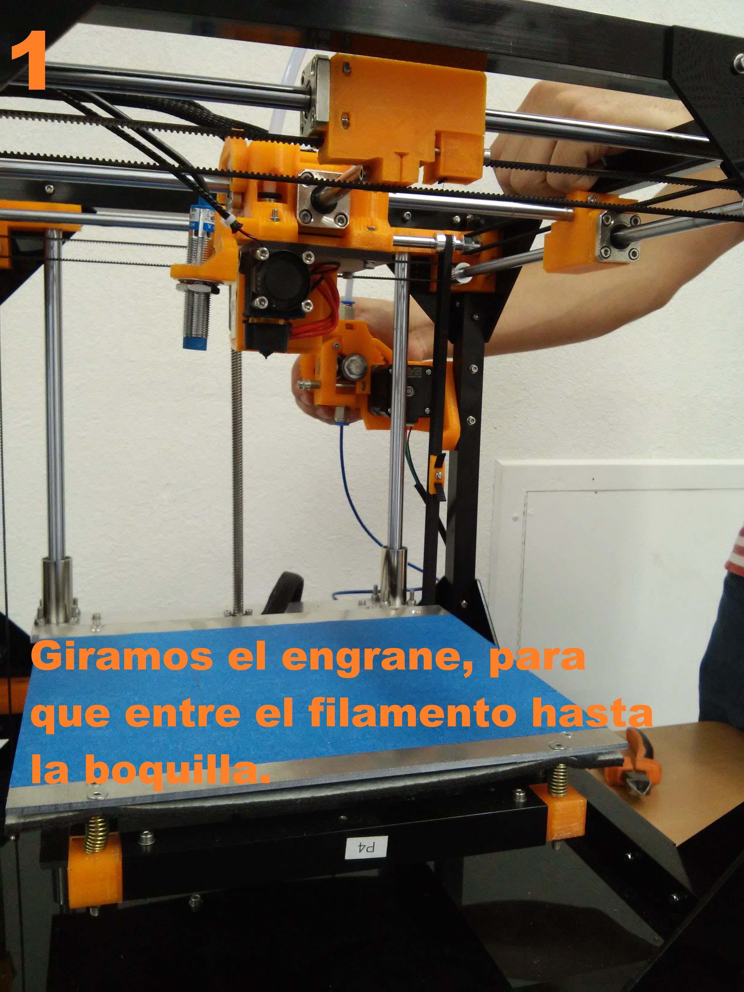
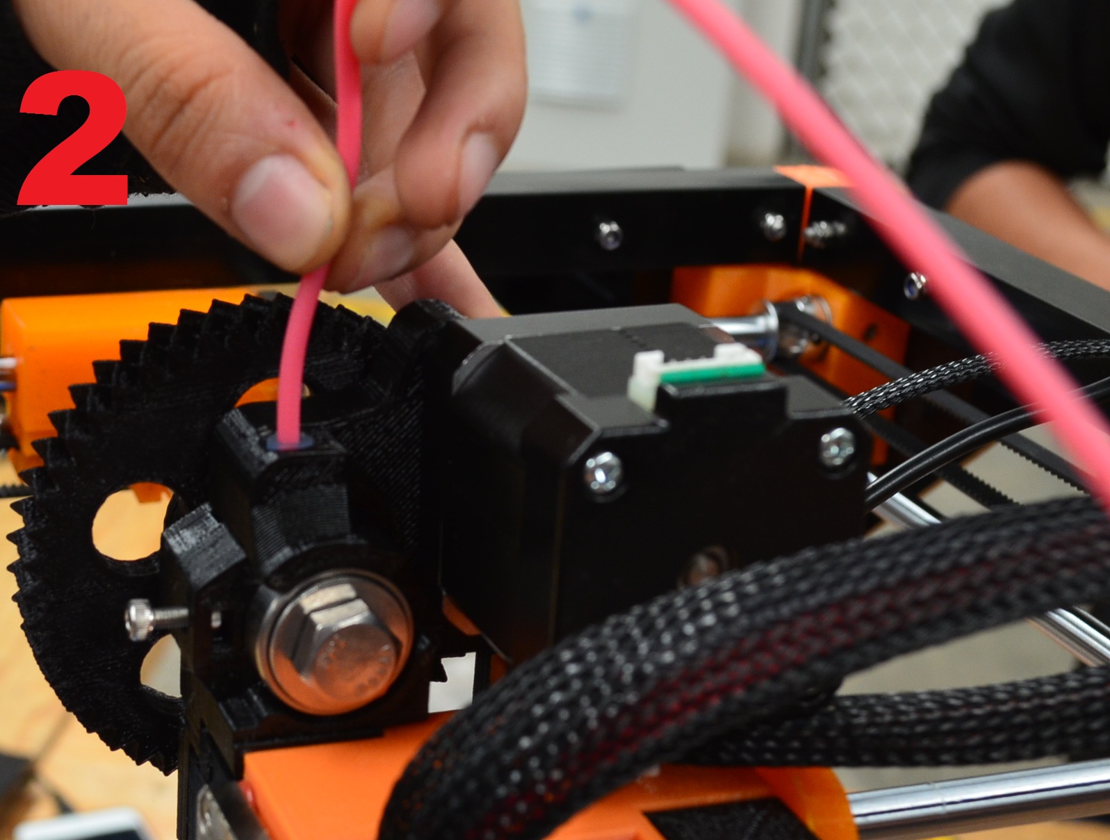
Step 4
When the noozle reaches the temperature, turn the big ger of the extruder in order to make some of the filament get out of the noozle. When the material comes out of the noozle then we are sure that is well loaded.
Note
To unload the filament the proces is similar; heat up the npzle and then turn the engine clockwise until all the filament is unloaded.

Step 5
To print form an SD card we have to save a GCode on it, we can generate a GCode with the following steps:
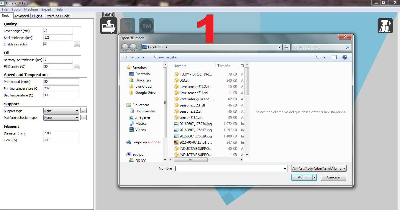
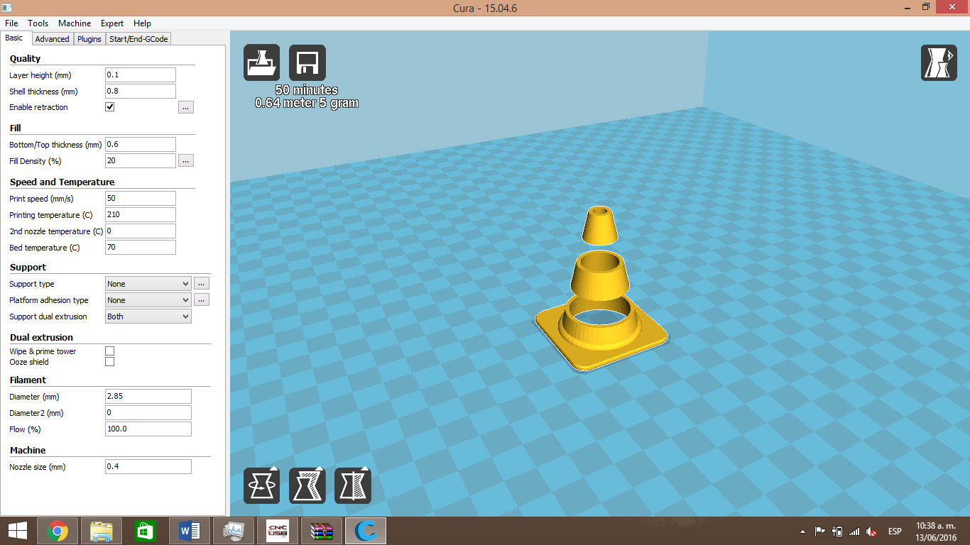
1.- Open Cur and click on “Load”, it will open a window where you will find an STL.
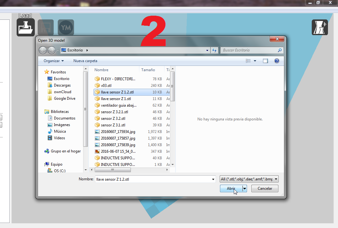
Select an STL and click on “open”, it will load the model on Cura
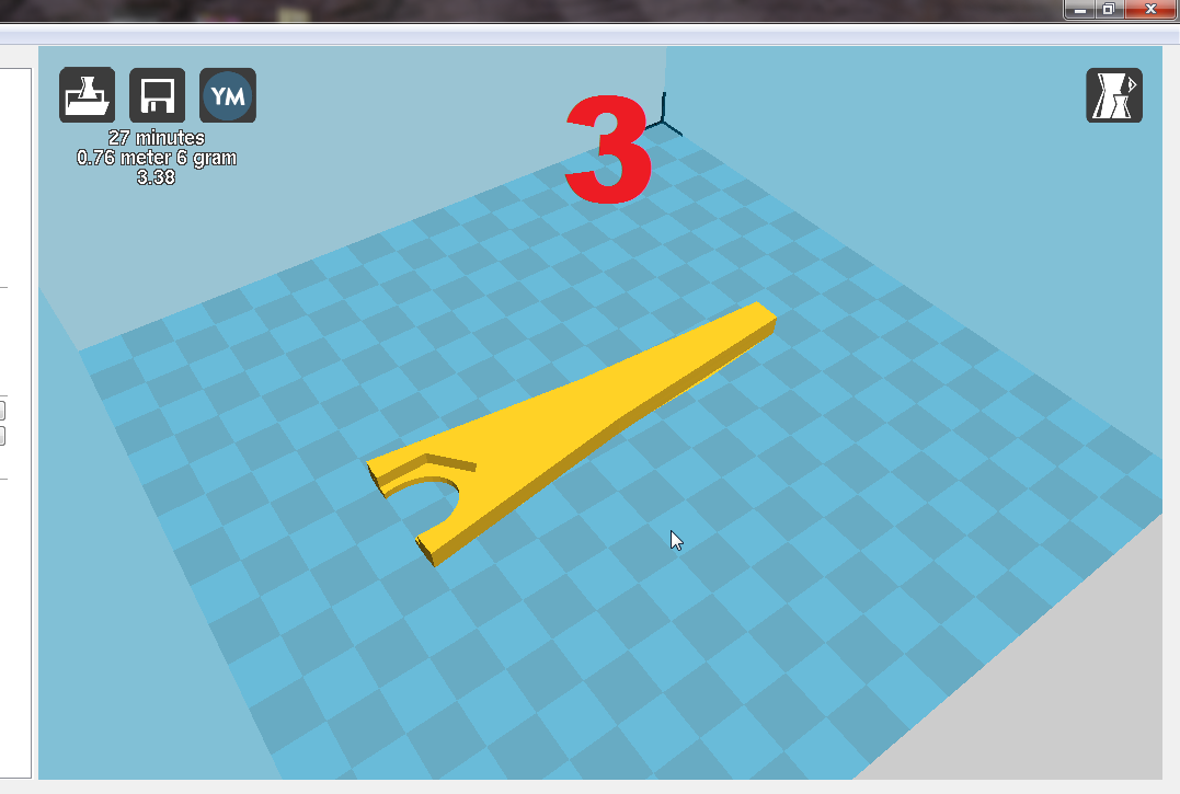
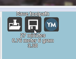
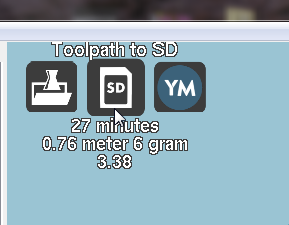
Remove the SD card from the printer and insert it in your computer, observe that the icons change when you insert the SD, click on the save icon to save the GCode on the SD card.
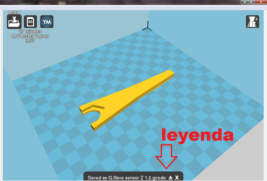
Now, you hve to wait to the “Saved as…” message to remove the card from the computer.
Step 6
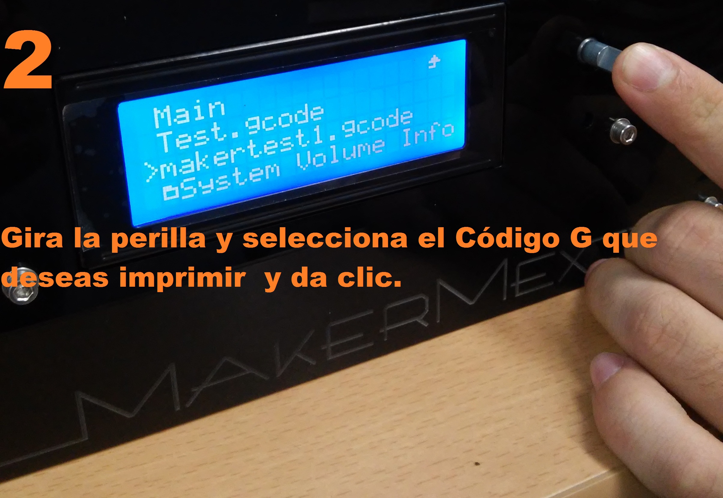
Now you can insert the SD on your printer, turn it on, select “Print from SD” on the sccreen, and select the model you want to print.
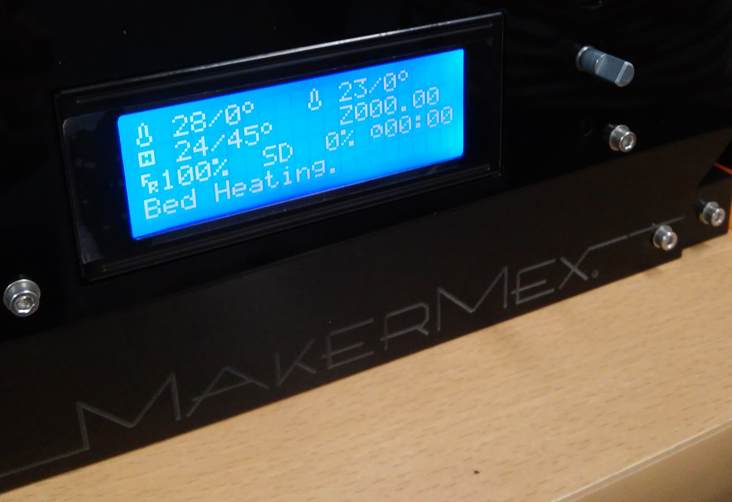
The printer wil start to heat the hot bed and then the noozle according to the parameters configuring in cura.
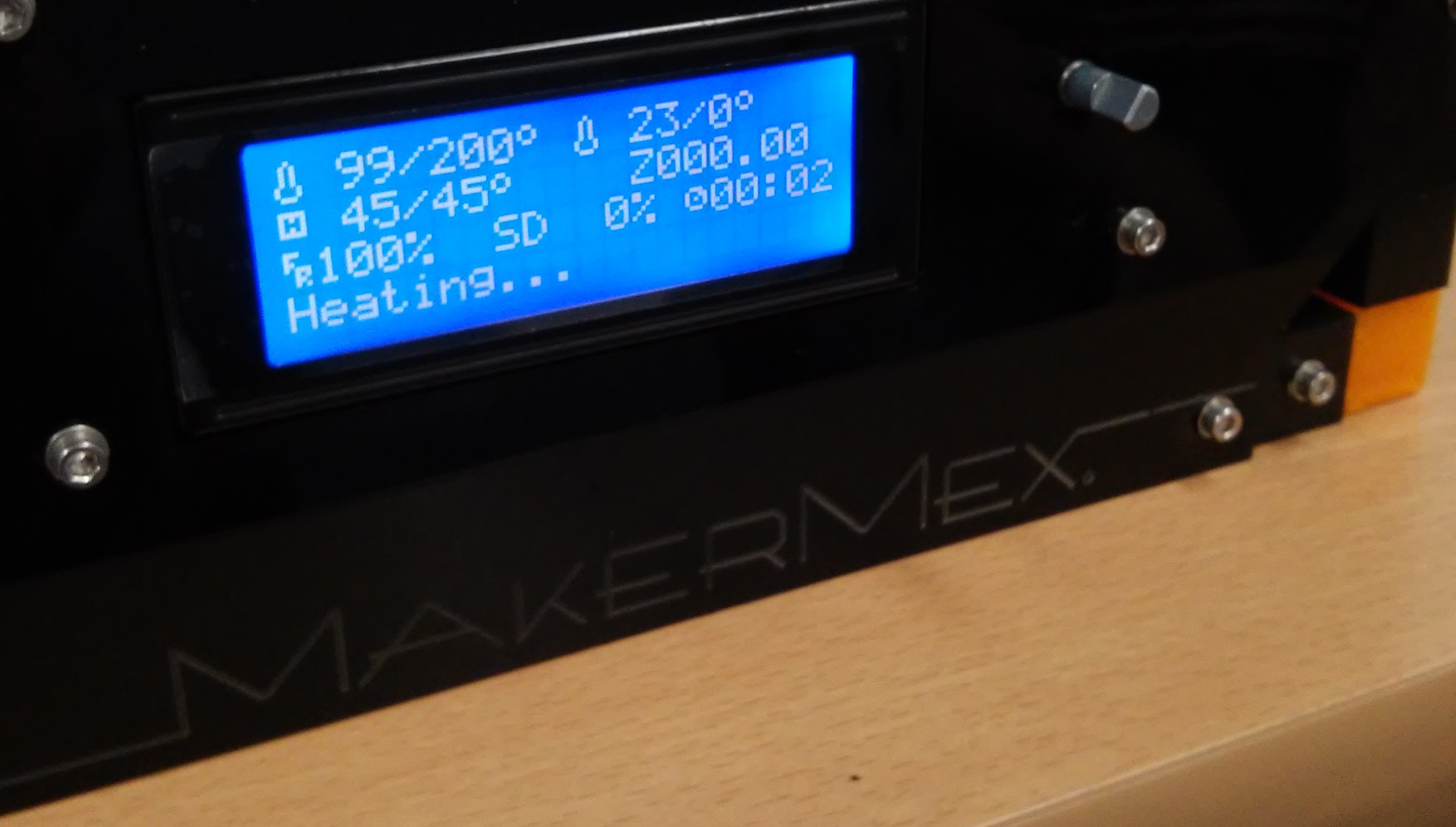
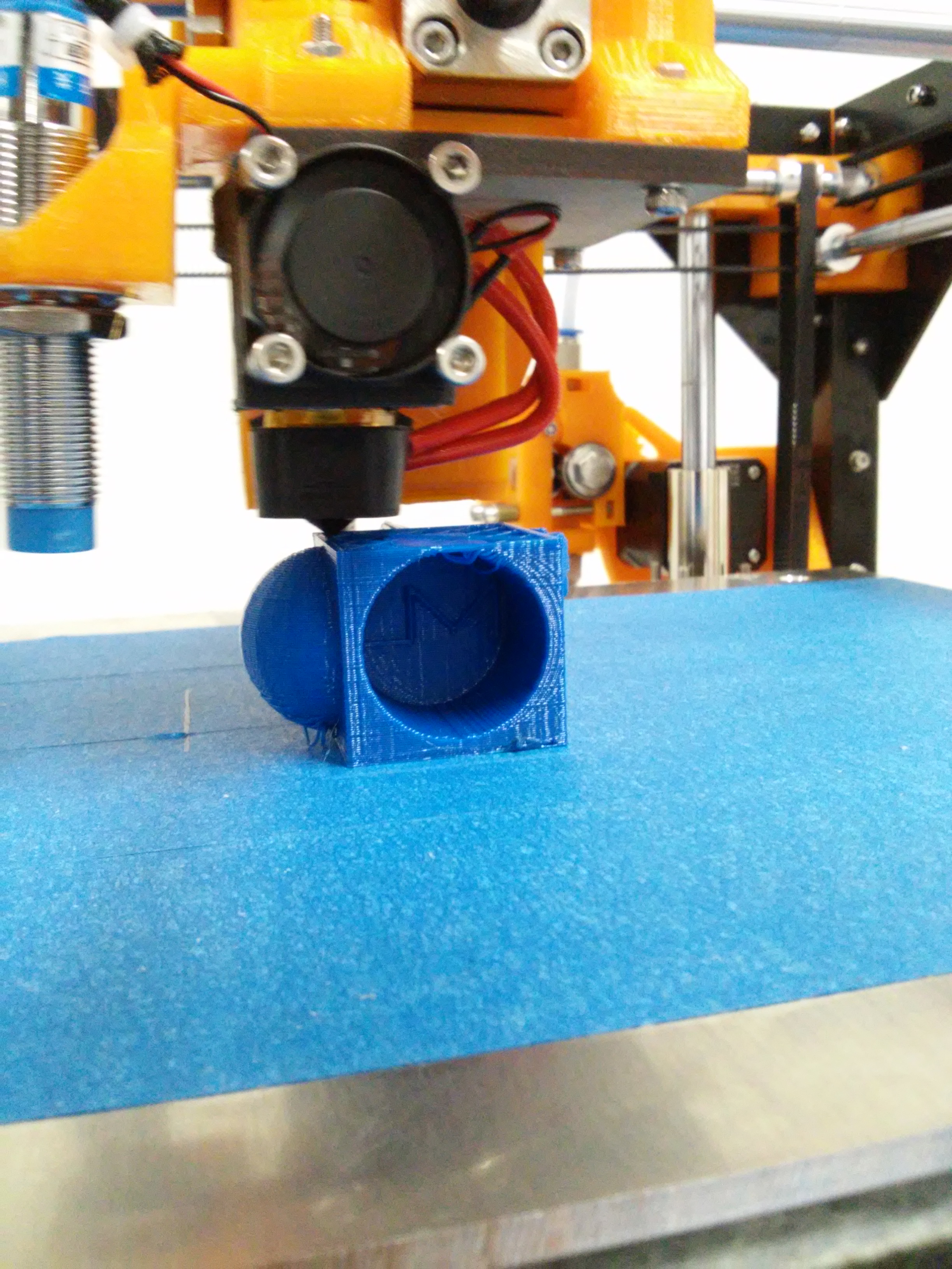
When the noozle and bed reach the temperature configured the printing will start, the first thing it will do is to move to home and will purge some material, then will go to the enter of the bed to beging the print.
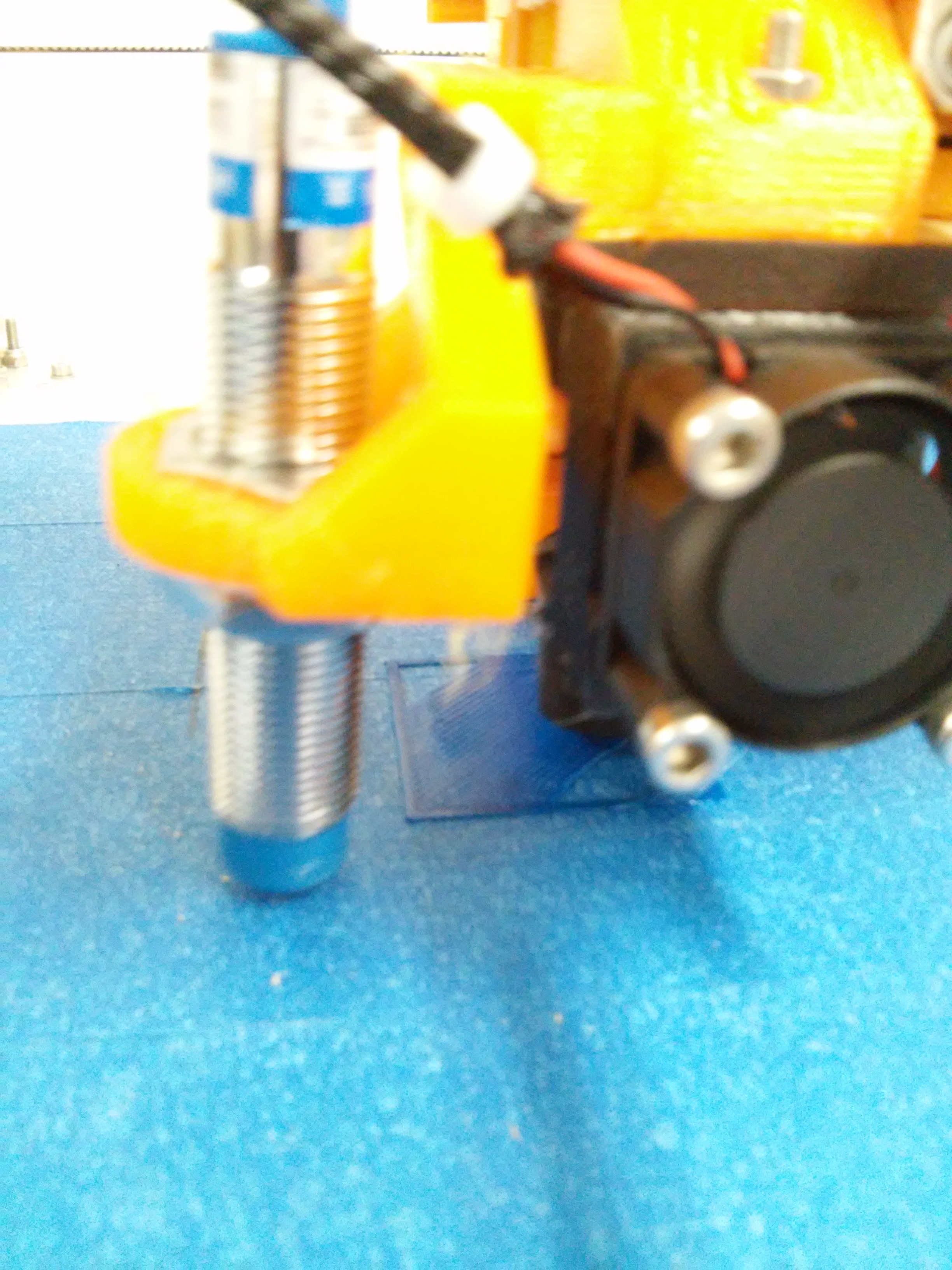
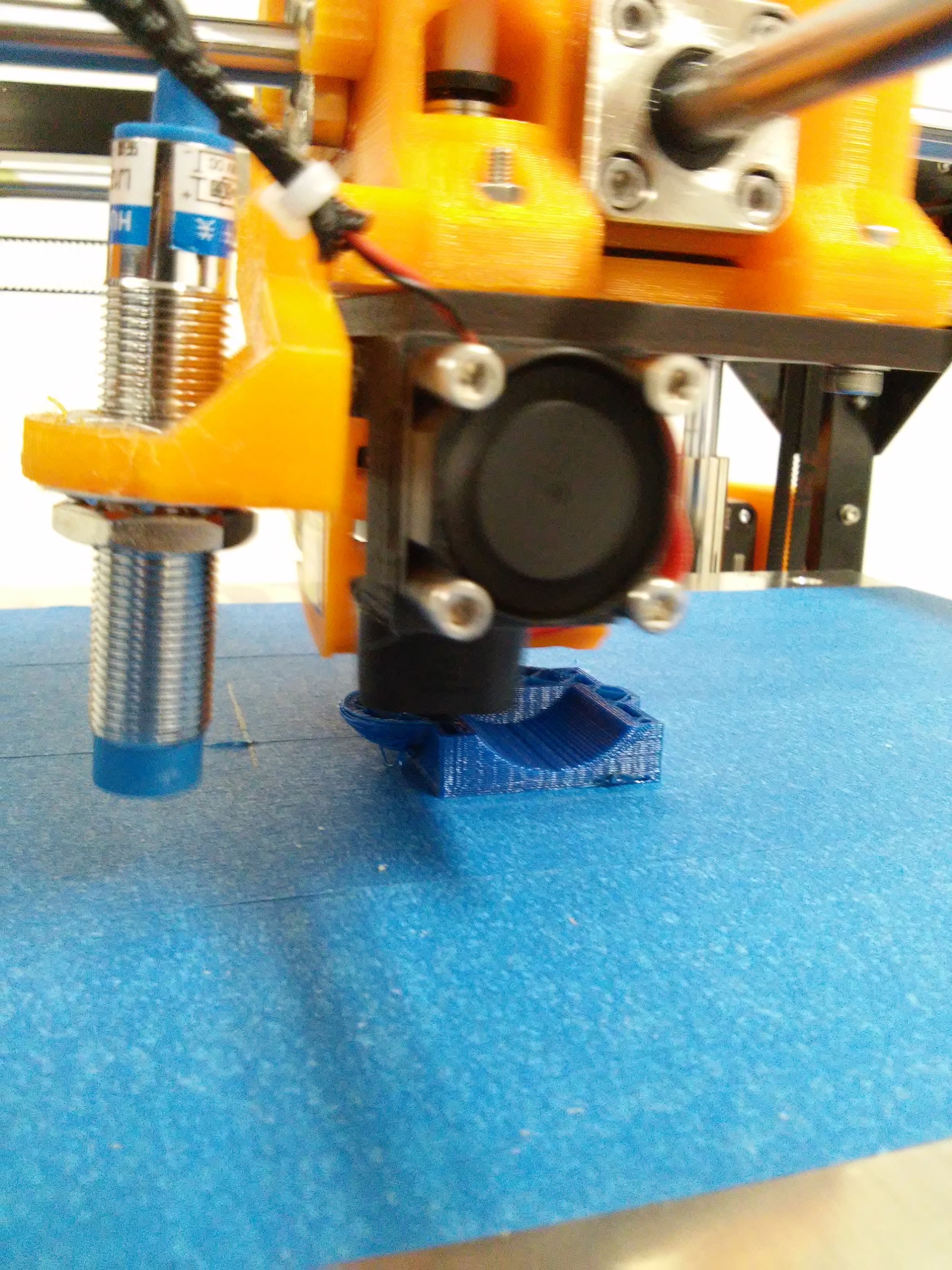
The first layer is the most important it need to be well stiked to the bed, see the image as a reference.
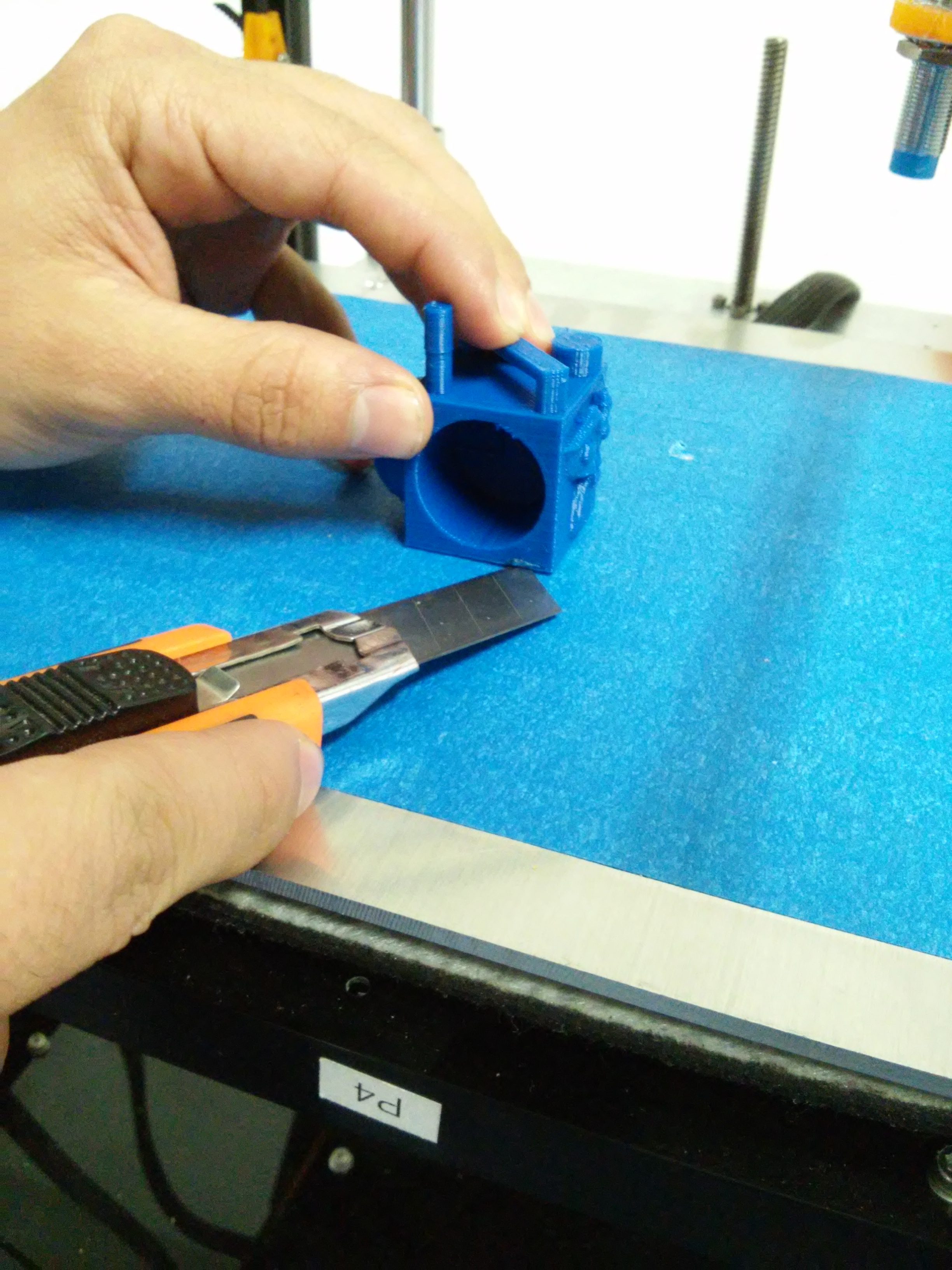
When the print has finished we need a knife to remove the final piece from the bed.
Modules
Flexy Module
With this module you can print flexible materials, like Ninjlex, TPE, PLA soft and other more. Follow these instructions to learn how to use your flexy module.
We will identify the componets of the module to install it correctly,
| 1.- Lower module (noozle) |
| 2.- Superior Module (Extruder) |
| 3.- Filament Guide |
| 4.- Extruder motor Wire |
| 5.- Three M3x16mm screws |
Note
All thes part are unique and fundamentals to install and use the Flexy module.
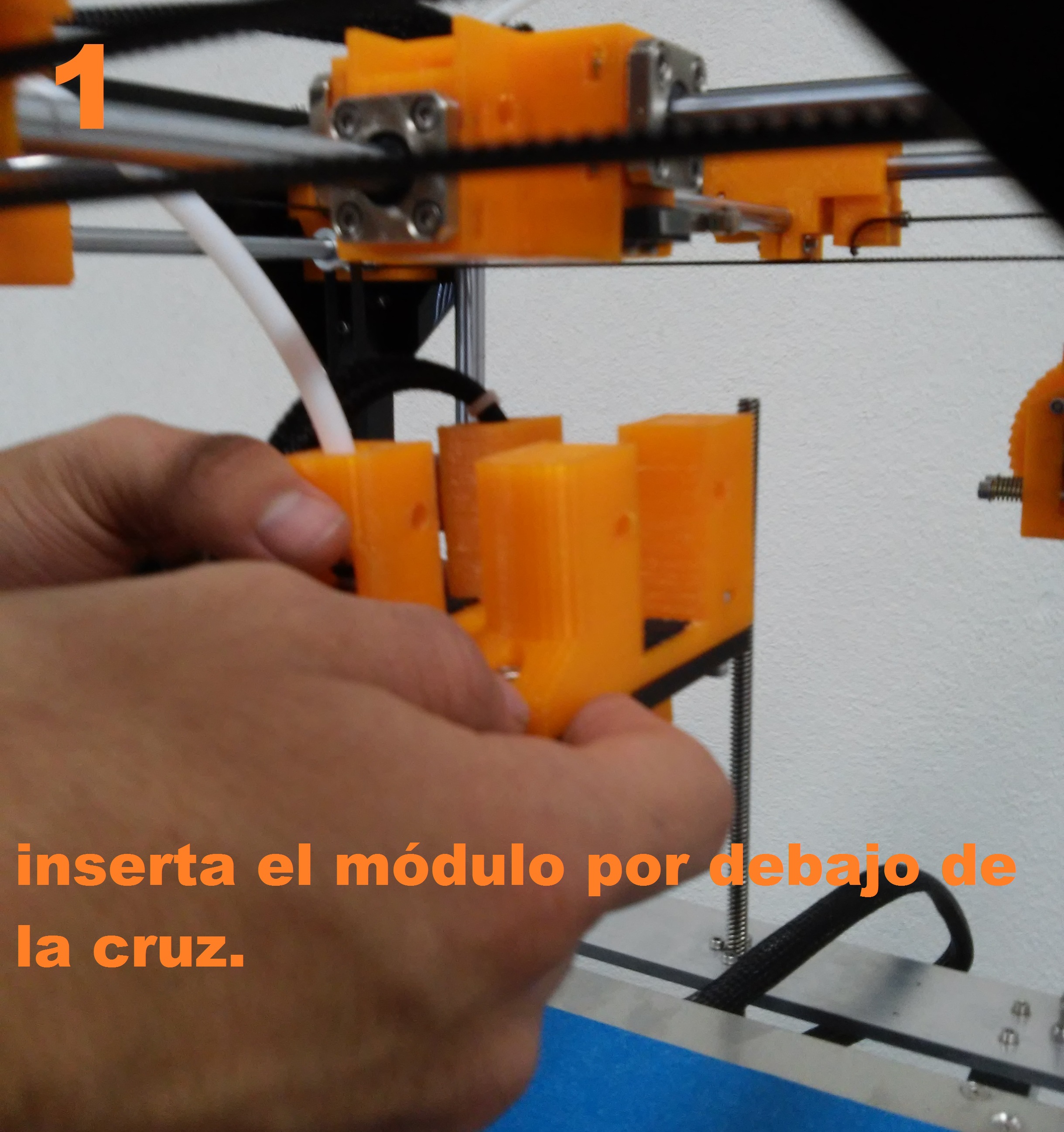
Step 1
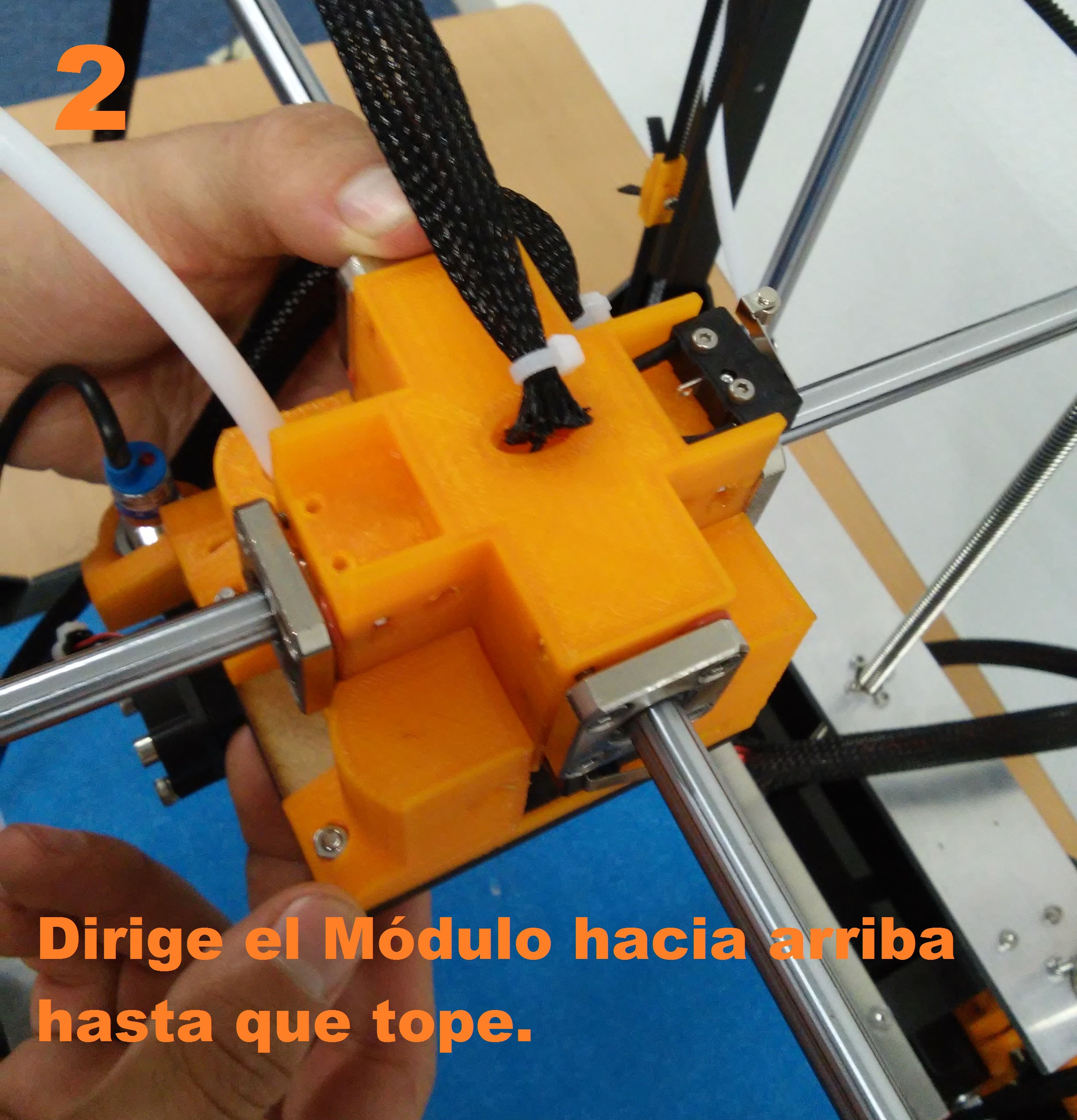
Put the Lower Module under the cross until it reaches to the limit.
Step 2
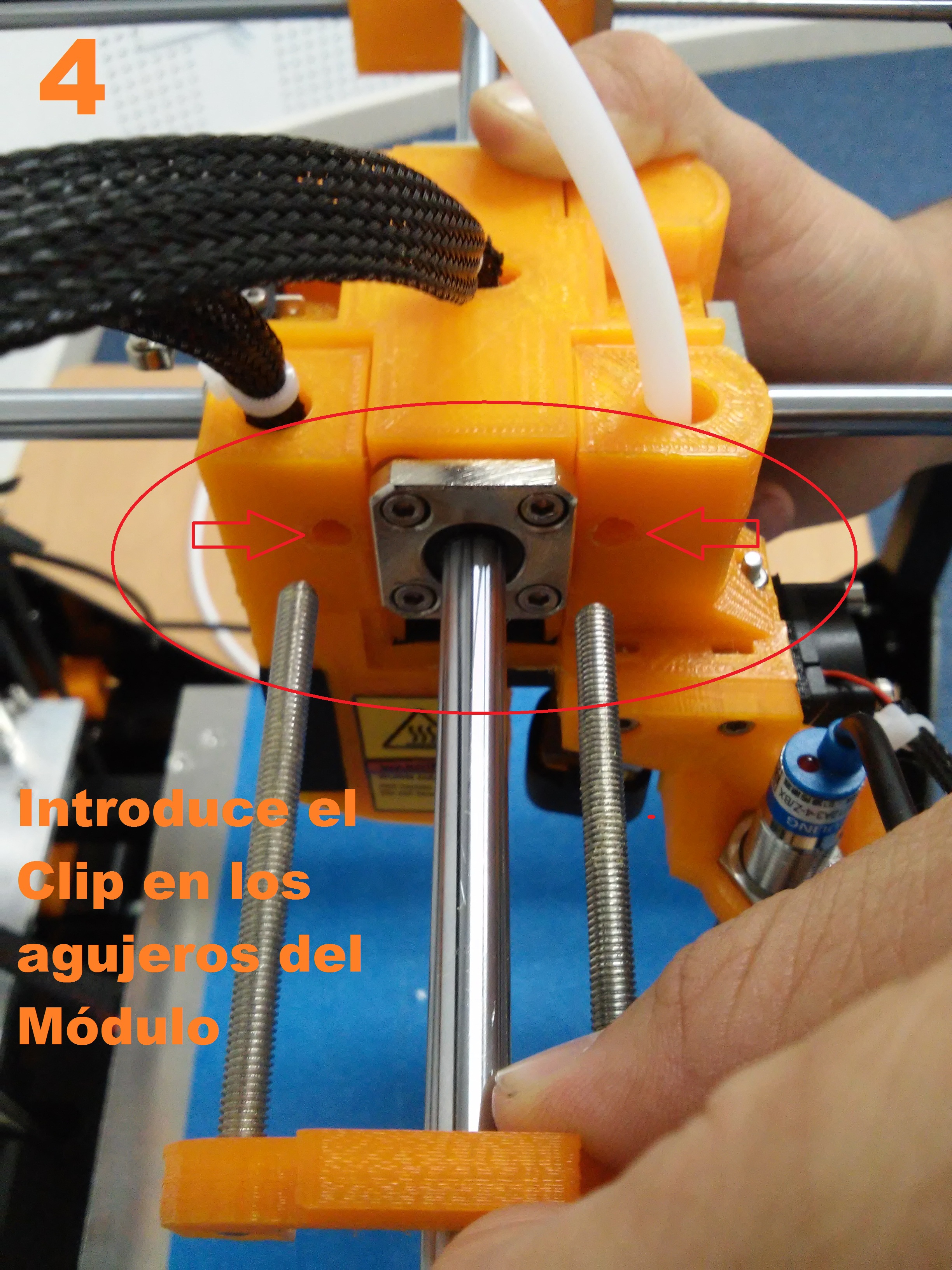
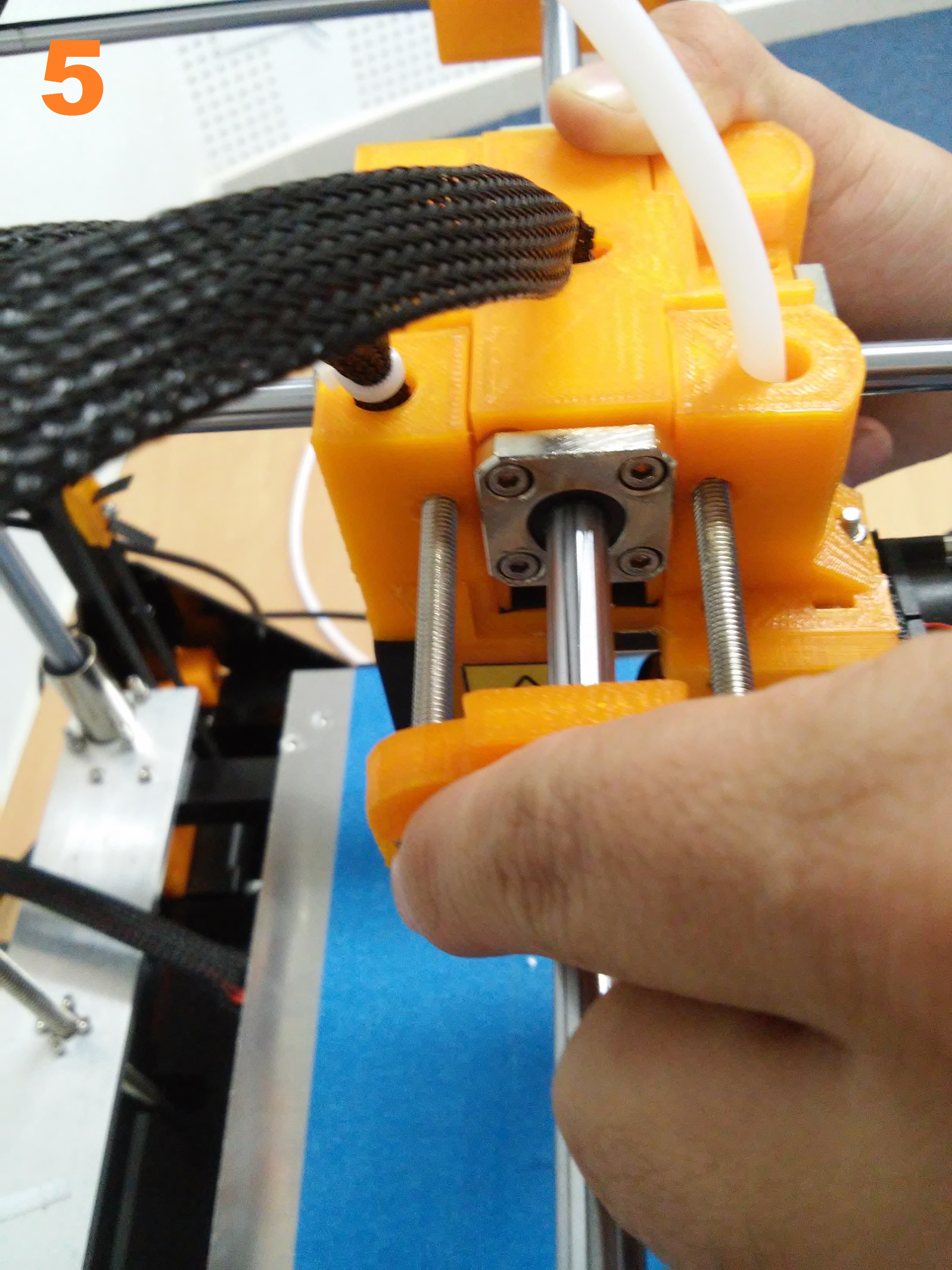
Insert the clip to hold the module on the cross.
At this point the lower module is attached to the cross.
Step 3
Put the Higher module over the lower module. This part i very mportant because is the part that provides the filament to the noozle.
Higher module must fix perfectly on lower module.
Step 4
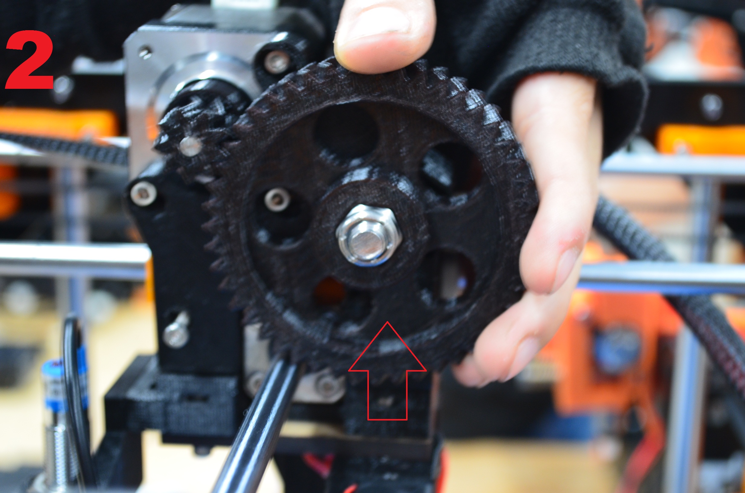
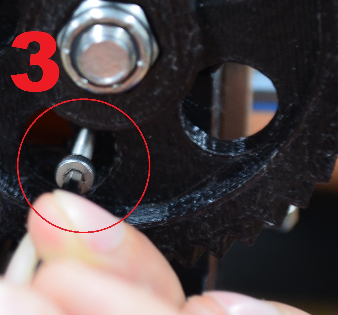
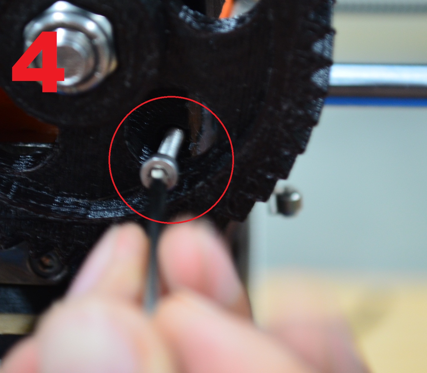
Now, put the M3x16mm screws to hold the two parts of the Flexy Module. use an “L” 2.5mm Allen wrench.
Turn the gear a little to be abe to insert the screws in the part showed on the picture.
Step 5
Put the filment guide on the top back profile as shown in the images.
Step 6
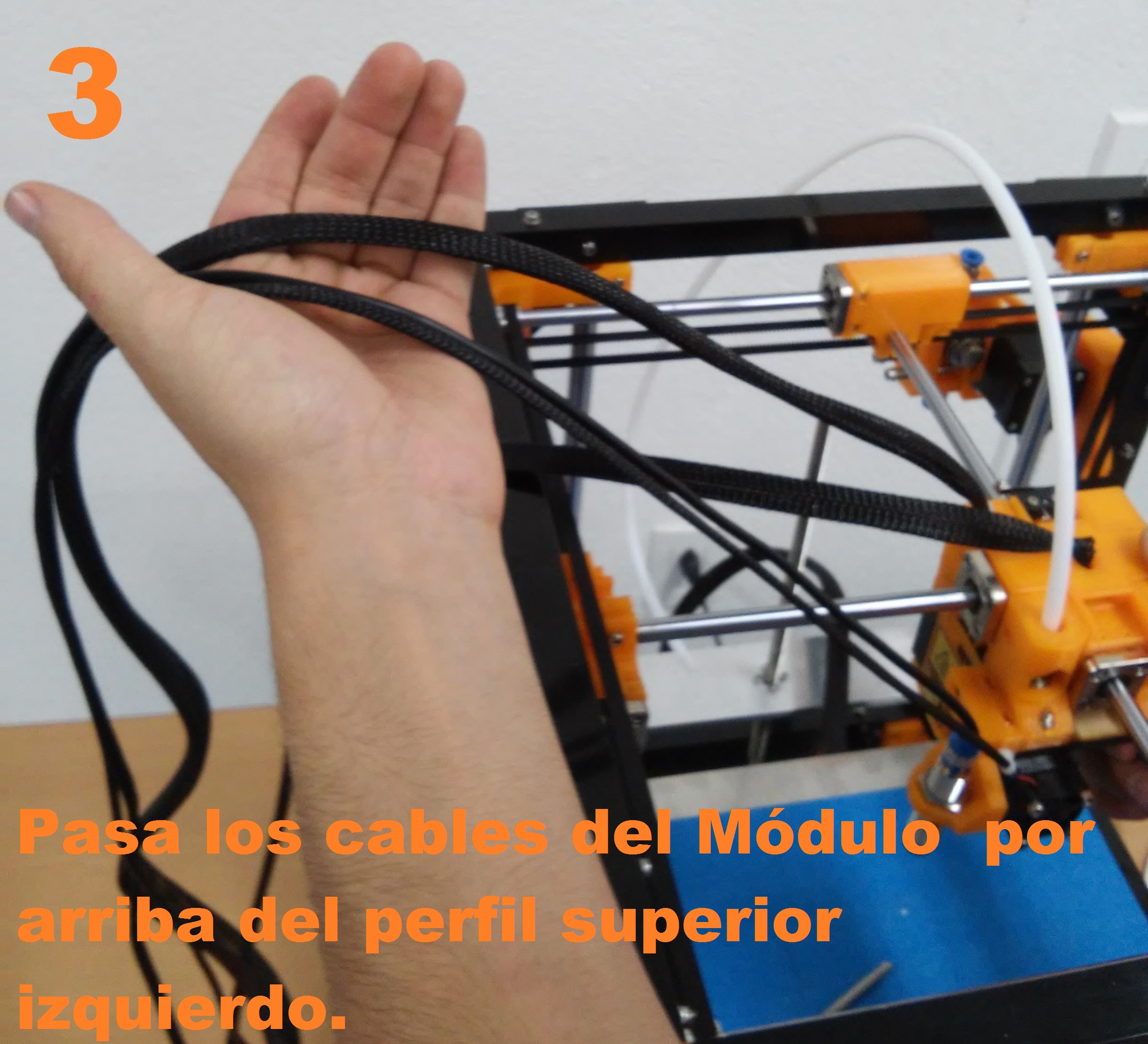
Conect the wire of the module, ass the cabless over the top left profile and plug them.
Step 7
Now conect the motor with its cable
Note
Remember that this cable is different to the one already connected, is a motor cable but has a paticular feature for the flexy module.
First we connect the motor
Now we connect the cable in the input marked as “M1” in the back of the printer, if there s already connected a cable unplug it and connect the cable that comes with the module.
Step 8
Lastly, we load the filment and a G code to print, follow the steps below to oad the filament in the noozle.
| How to start to print |
|
|
|
|
|
Note
- Ninjaflex and TPE 225°C
- PLA soft 208°C
When the noozle reaches the temperature, put the filament into the filament guide until the hole of the top module, then turn the gear clockwise until the filament reaches the noozle.
When a litle thread of filament comes out of the noozle, the filament is ready to use.
Now turn off the printer and turn it on again, this will reset the electronic board and will cooldown the noozle with the fan, it is important to dont turn down until the nooze cools down to avoid a filament jam.
Step 9
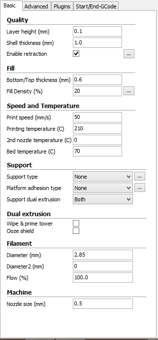
In this part we will configure the printing parameters, remember that temperature depend on the material to use.
|
|
Here you are the rest of the parameters
Note
For PLA soft we use these parameters.
With these parmeters whe are ready to save a G Code in our SD and print from itas we did in the First print section.
Dual Extrusion Module
GENERAL
| Thecnical features |
|
| General features |
|
MODULE INSTALLATION
To start printing with two materials you must install the dual extrusion module in the module support of the MM1
We will nstall the second extruder the same way we instlled the first one, the difference is that this one goes to the right.
you must connect the second extruder in the 6 pin cable with the label “2”. The extrusion gear and the inductive sensor must be installed the same way than the single module.
CURA CONFIGURATION
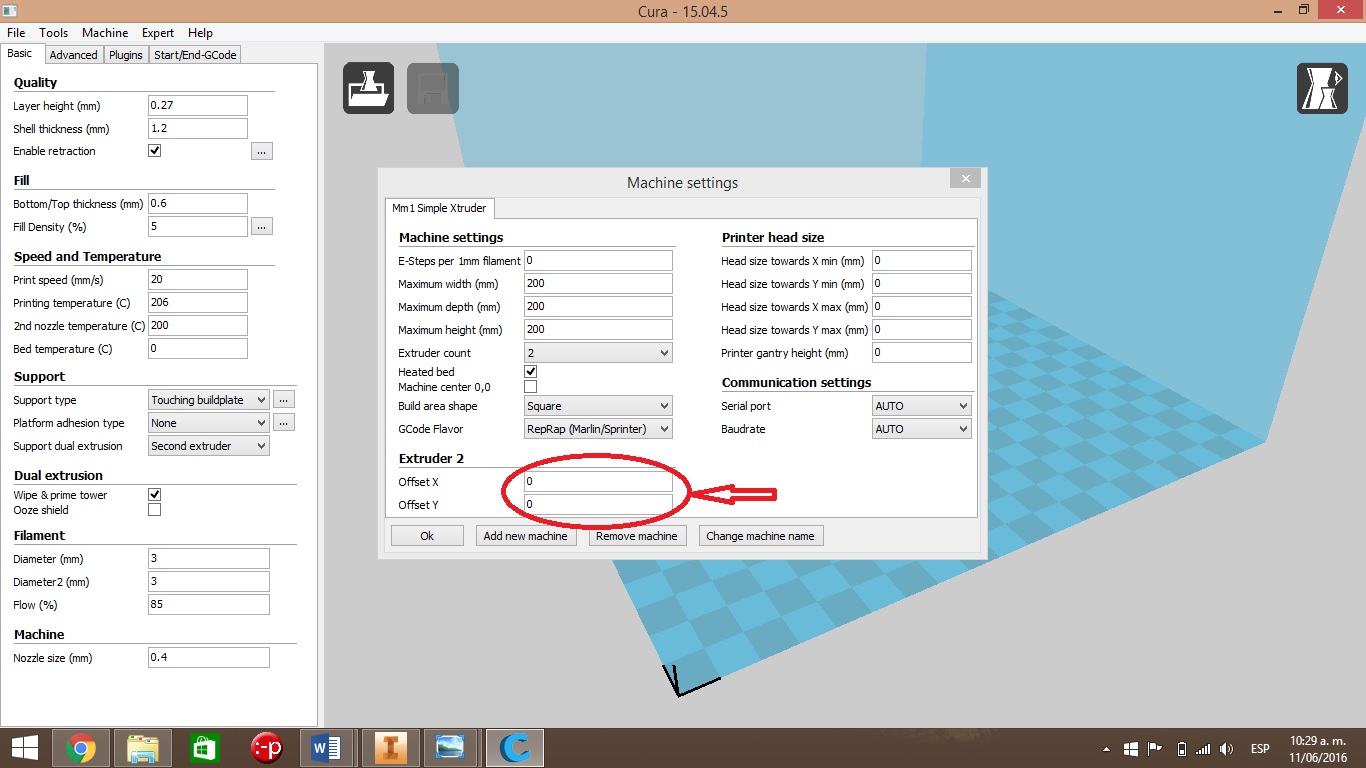
You have to adjust the machine parameters in Cura in order to use the dual extrusion module
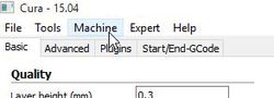
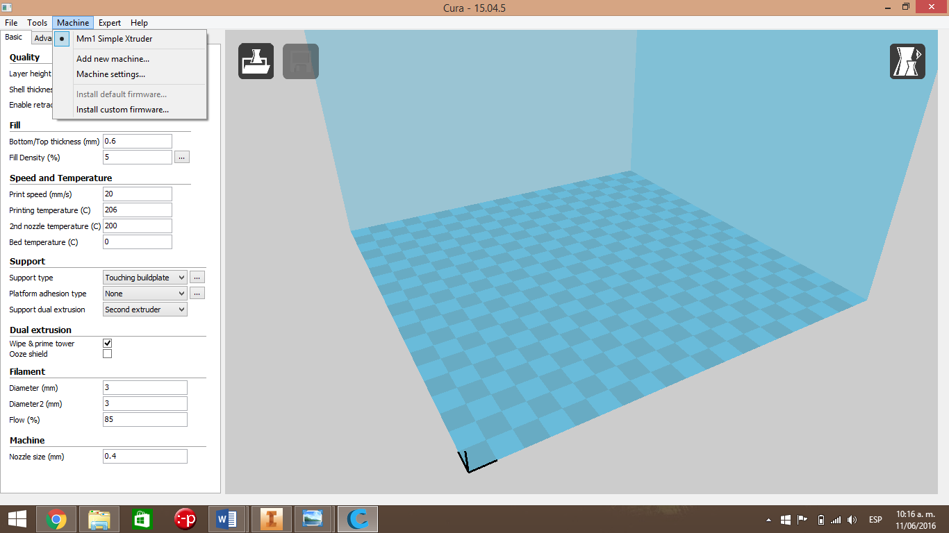
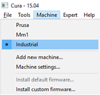
1.- Go to de “Machine” menu.
2.- Once in “Machine”, go to “Machine settings” and click.
Go to Extruder Count, click the dropdown, select the number 2 and click OK.
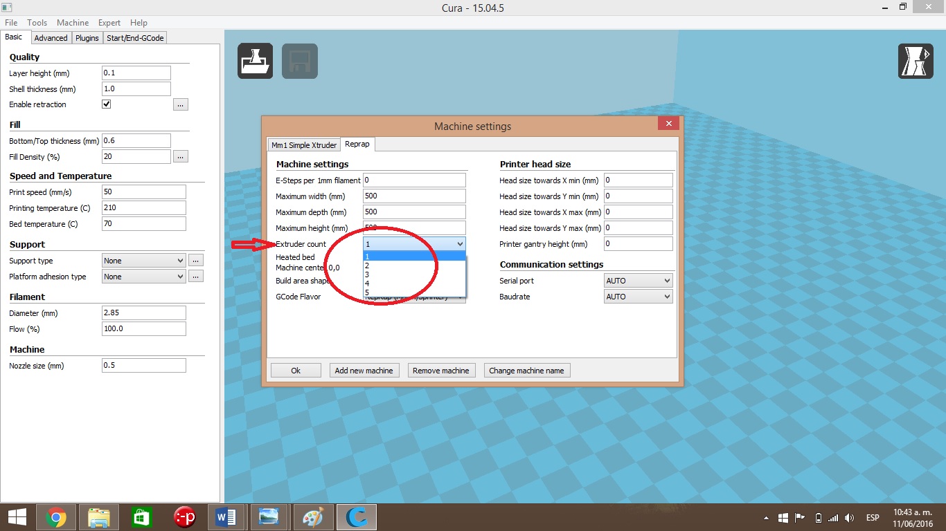
4.- In the same screen, Machine > machine settings > verify that the offset is zero.
5,. Now we will modify the printing parameters according to the material to use
5.1, Now we will modify theshell thickness, the infill, the retraction, and the printing speed.
- The Layer height is the height of each layer and the shell thickness is the thicknes of the wall.
- Fill density is the material used inside the printed figure, usually we put 40% for functional parts; and 15% to 20% for visual prototypes.
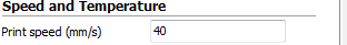
- Now we configure the printing Speed in mm/s.
- Select te temperature of each noozle according to the printing material. as well as the bed temperature.
- Now lets define if some support is needed, for this example we will do the support with the second noozle, go to “support type”.
- Go to the “Support dual extrusion” option and select “second extruder”.
- For this print we will check the “wipe & prime tower” option, that is a support tower used to verify that we dont have layer shifting
- Now, we will modify the default filament diameter (2 mm), we will use the same diameter than the used in noozle 1 (2.89mm or 3mm)
5.2.- Now, go to “Advanced” to set the retraction speed, usualy it should be 15 or 20mm, the distance hould be between 5mm to 8mm.
Setting mterial profiles
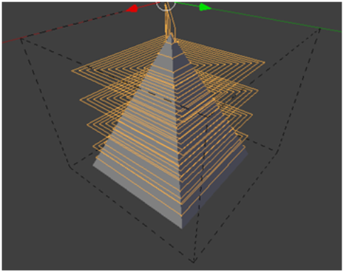
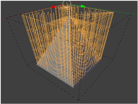
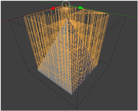
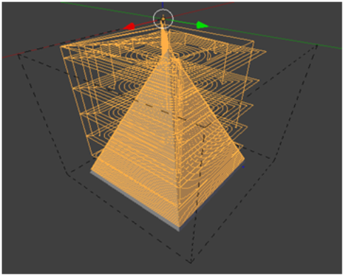
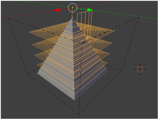
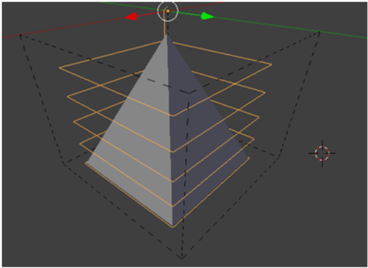
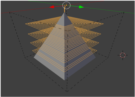
You will need a model separated in two parts, making Cura to know wich part will print each extruder. There are many models ready to print, or you can make and prepare your own model using a 3D modeling software like Blender.
Import the first part of the model in cura, that will be printed in the first extruder.
Next, import the second part of the model, that will be printed with the second extruder.
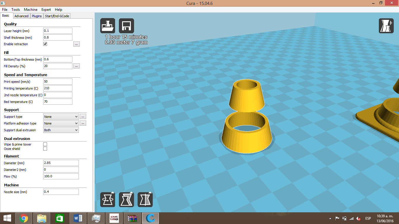
Lastly, we right click on the Cura workspace and then select “Dual fusion de extrusión”, this will join the two parts in a single model.
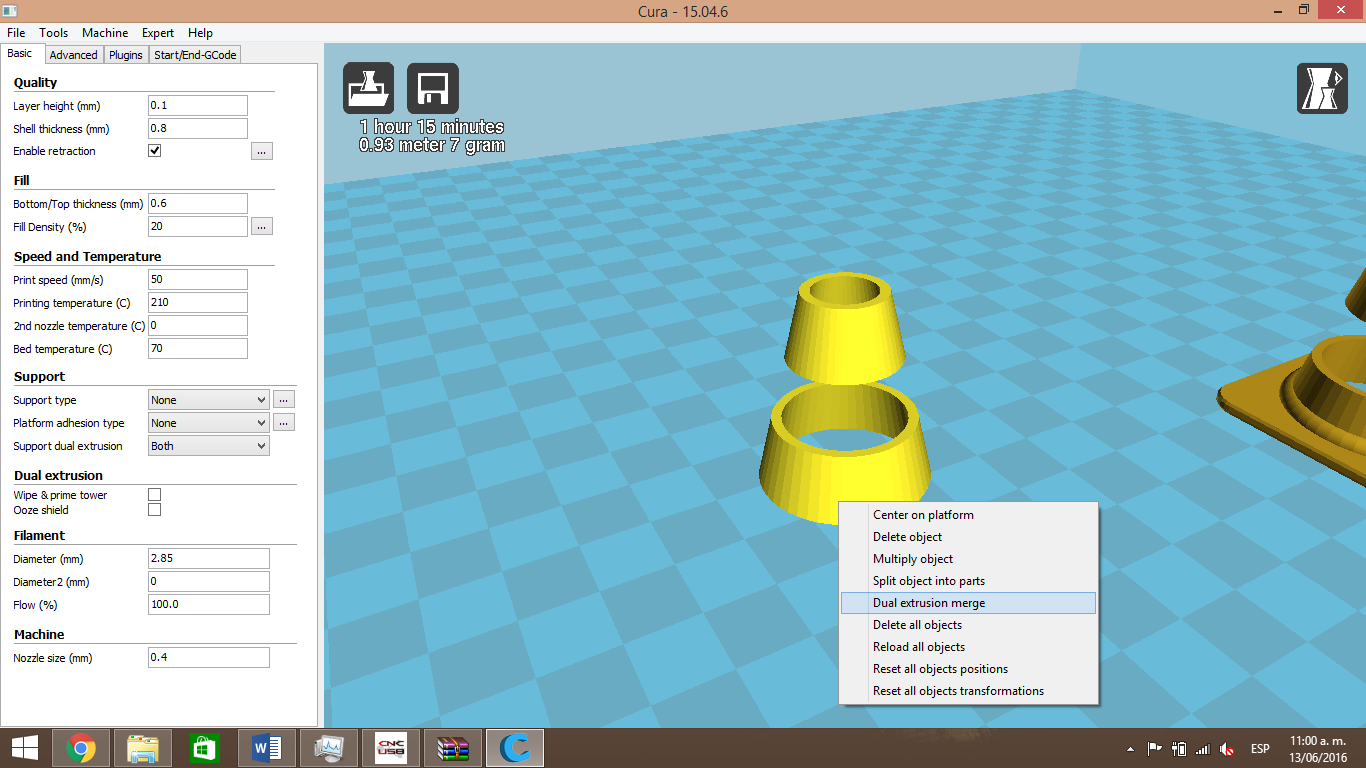
The piece must look like the image, the second extruder will print in red.

Now, we have to save the Gcode in an SD card, the same way we did it in our first print. turn on the printer and plug the SD card to print from it.
CNC Module
MANUAL FOR MACHINING WITH CNC MODULE using BlenderCAM
SOFTWARE DESCRIPTION
What is BlenderCAM?
Blender CAM is an open source solution for artistic CAM - Computer aided machining - a g-code generation tool. Blender CAM is an add-on for the free open-source Blender 3d package.
| FEATURES |
|
Note
More information in http://blendercam.blogspot.mx
BLENDER-CAM INSTALLATION
To install BlenderCAM, clic on the link to de software official website
| Link de descarga http://blendercam.blogspot.mx/p/download-and-installation.html |
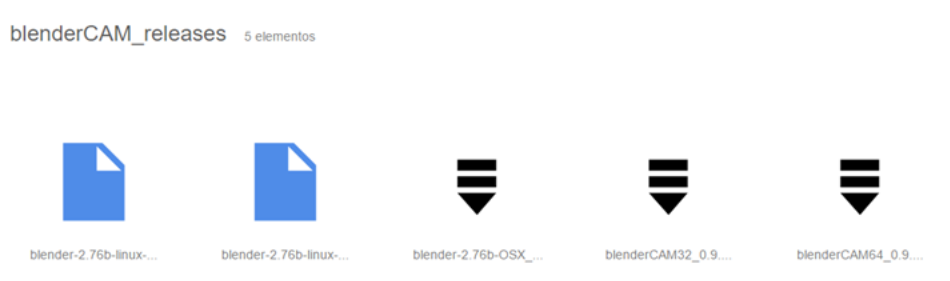
Open the tab: “Download and installation” then clic on “Google Drive repository”.
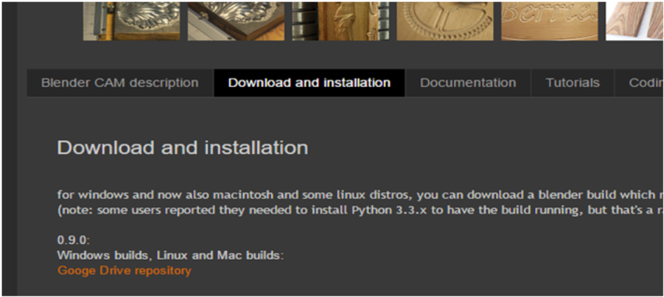
In the next tab we select BlenderCam for our Operating System
WORK AREA DESCRIPTION
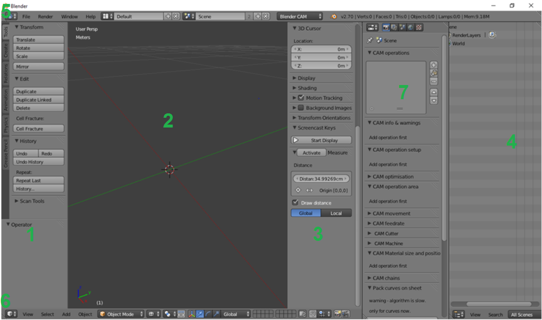
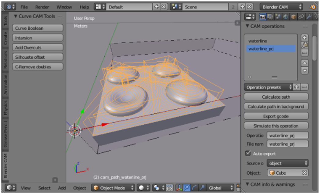
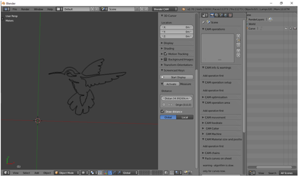
On the image 1, you can see the BlenderCAM 2.70 start screen,now we will describe the working area in a basic way.
1.- Is the tools panel, the sshortcut is [T] key, here we cn create a basic figure, move, scale, rotate, without modifiyng the object. 2.- Is the working aea, the black cross is the cursor, all the objects will be created in its position and tht position will be the center of the model. It can be modified in the properties panel (3) or left clicking inside the area.
Right clicking in an object we can select, rotate ormove them freely. we zoom with the mouse scroll.
3.- Is the properties panel, its shrotcut is the [N] key; on this panel we can modify the position of the object and cursor on the workspace, you can modify multitexture shading, and other options. 4.- This is the operations tree, where we can find each object in the area an the operation type. Here we can chamge the vie to transparent, select objects and extract renders. 5,-Is the preferences window, here we can modify the Blender environment, document propertie, import/export, change de window type etc. 6.- Is the 3D view window, where we can modify the elements view, wireframe mode, layer map, and some modeling tools like SNAP. 7.- Is the operations panel, CAM chains, in some times after the installation of BlenderCAM the CAM Mode is not shown, now we will explain how to access CAM mode and how to activate the CAM plugin to the best exploitation of the software.
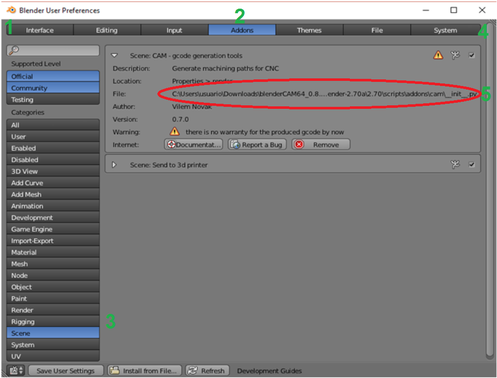
8.- Go to user preferences Panel, select File, open the User Preferences folder. Also you can use ‘Ctrl + Alt + U.’ 9.- In the bottom part you can select the Add-ons Tab. 10.- Select the Scene categorie. 11.-In this part you can find the CAM Add-on, to activate t click on the box as shown in the image. 12.- be sure the path belongs to the one of the Add-on in the image.
The second step is to guide BlenderCAM to find an alterntive path for the Add-ons. When BlenderCam is executed, it will look into the Add-ons pathfor the scripts, this way you can use an Add-ons external source in Blender.
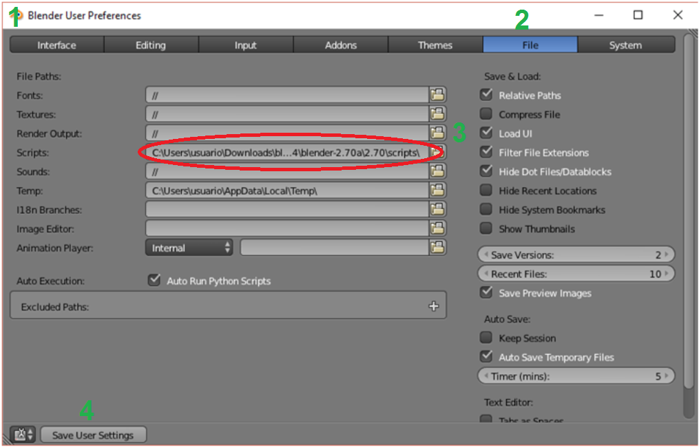
13.- Go to User “Preferences panel”, select “File” and open the folder “User Preferences”, also, you can use the following command: Ctrl+Alt+U. 14.- In the top part of thw widow select the “File” Tab. 15.-Go tp segment “script” and select the folder of the Blender CAM scripts. 16,. After tha, select “Save User Settings” to keep these configuration. 17.- Finay restart Bender.
Enter CAM mode
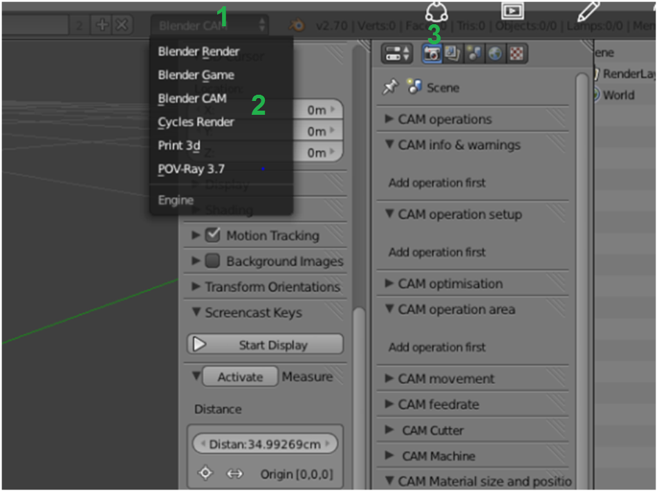
- Go to the top bar (User preferences), open the “Engine” window
- Select Blender CAM mode
- Go to the operations paneland select the render.
We can start to work with BlenderCAM mode , in this example we only make the graving process.
CAM parameters description
CM operations
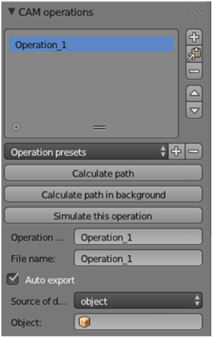
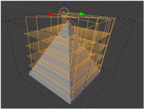
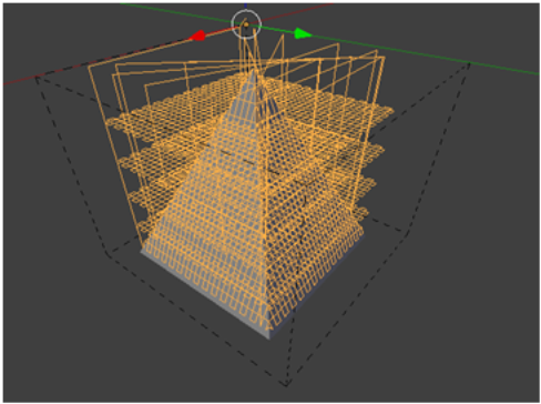
- Calculte Path: Calculates the operation to perform, also it shows a graphic simulation of the CNC path. Fo that, we have to add the operation selectig the object. hold the button pressed and wait a few seconds.
- Calculate path in background: this unction calculates the path, while allows you to continue working on other operations, is important to save the document before you realice any calculation.
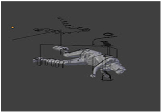
- Simulate this operation: To generate this simulation, a new object is created over our model that we can move on any desired axis. This object can be scaled, subdvided and its resoluton can be increased in the optimiztion panel.
- Operation name: In this field you an cange the name of the selected operation.
- File name: This is the nameof the generated gcode, the file extension will be determined for the selected g-code postprocessor.
- Auto export: if this option is activated, the G-code will be automatically generated and the file will be saved fter the calculations
of the operation in the same folder where BlenderCAM is saved.
- Source of dates: Here you select the set nd type of objects, it can be aan image or an objects group or a single object.
- Object, here appears the mesh or curve you are workig on
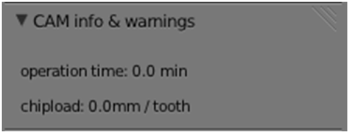
CAM info & warnings
CAM operation setup
Strategy, in this option we choose the process that will be executed in our object, next we will show the following stratgies or processes.
PARALLEL: paralel paths in any angle.
CROSS
BLOCK
SPIRAL
Right for curve objects
- CIRCLES
Right for curve objects
- WATERLINE EXPER.
Perform better finishes, is an experimental user process.
OUTLINE FILL
CUTOUT
This process will be used for graving, this marks the contour inside, over or outside the line of our object or curve
POCKET
DRILL
Detects circles or squares in any 2D curve and converts them into a drilling operation
- CARVE
Proyects 2D or 3D curves in the surface.
Some of the operations or estrategies combine with the following parameters.
- Distance between toolpaths: Is the distance that will hve the paths.
- Distance along toolpaths: Influides in the mechaning precission, is the density of the path of the operation.
- Angle of paths: this parameter turns the paralell and transverse strategiesto the specified amount.
- Paralell step back: This uses a posterior movement of the machine for the finishing of the surface. tke in count that this will slice the aterial at duble speed than the dstance between paths, if you dont know ahat al this means, don’t use this option.
- Skin: Generates a layer in the surface for the finishing
- Inverse milling: invert de rotation of the drill, on the MM1 printer, you need a manual adjustment for this.
- Direction: this makes an spiral block process, it begins from inside to outside f the object.
- Carve depth: Decide the depth under the surface that will rough the operation.
- Don’t merge outlines when cutting: For this strategy it won’t fuse outlines, is very useful for PCB because you dont want to cross the lines.
- Use bridges: Cutout strategy that creates bridges automatically by parameters tht appear as: width,minimum height for the curve, etc.
CAM optimization
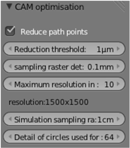
- Reduce path pints: Hels to rdce the number f commands in he Gcode. making the code shrter and easer to process for the machine.
- Reduction threshold in un: The direction of the path wll reduce to micrometers.
- Sampling raster detail: This is a very important for the memory use, and the speed of the software. BlenderCAM uses pixels to calculate the compensation positions of the cuts. If the object is 1 meter, the mage will be 10000 x 10000 pixels, that probbly will consume all the memory of your computer. verify the dimentions of the object before any operation.
- Simulation sampling raster detail: Practicaly the same as the last operation but applied to simulation.
- Detail of circles used for curve offsets.
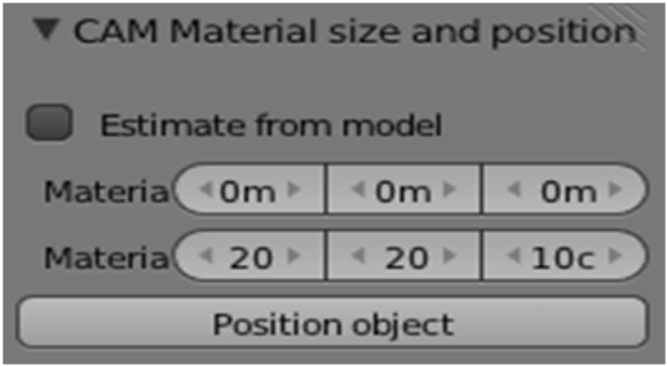
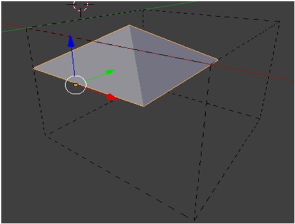
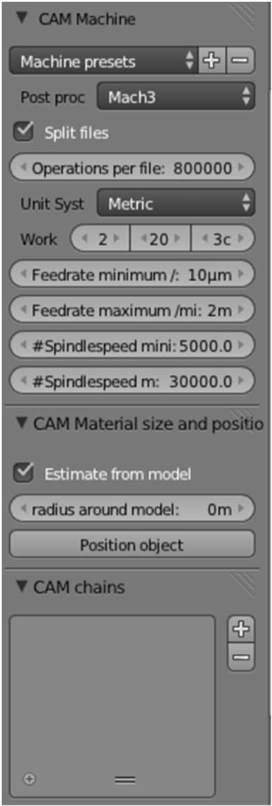
CAM Material size and position
Estomate from model: It assumes tat the dimentions of the object are the same than the working area, if this option is not activated an extra window opens tho set the dimentions.
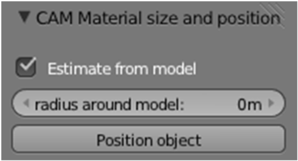
Position object, this option is very useful, it automaticaly send the object to the origin of the defined material.
CAM Movement
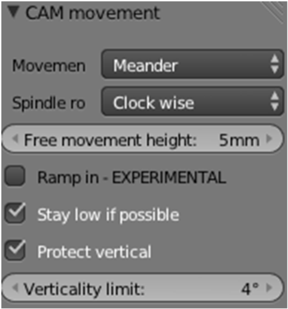
Movement type: It applies t som strategies, establis how the blade moves to the material.
1.- Meander: It will generate a zigzag moement in ny direction 2.-Climb: the cutter will turn to the feeding drection to produce a better finishing, less tention in the in the of the tool and require less energy to generate. 3.- Conventional: the cutter turns to the feeding direction. if the machne has kikcback that cannot be compensatted, then this is the best option.
Spindle rotation: thisperation defines the rotation of the spindle.
Free movement height: It is the height when is not machiniing. If we have a very high height the ressut is a very high duration because it takess more time to move at height.
Stay low if possible: Dont try toelevate the blade when it pass from one pth to nother, there ar some times when the tool fllow ways where the distance is smaller than the diameter o the tool, in this ocations ths opion will not damage the walls of the paths.
Proect Vertical: When the angle of the path is superior to the limit of verticalness, the movement will be vertical, this way the vertical surfarce will nt have inlination because of the distnce between the points of the path.
CAM operation area
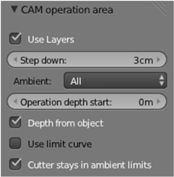
Use layers: it uses layer for the operation
Step down: this is the thicknes o the roughing layers.
Ambient: is the process accordding to the material that surrounds the object
| 1.- Around: this generates an outline to the object 2.- All: It generates a rectangle to the object/material |
- Depth from object: Establish the ddepth of the object and the totl depth of the opertion itself. Otherwise it can use the operations depth to do the ame manually
CAM federate
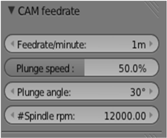
- Feedrate/minute: Speed of advance in a minute
- plunge Speed: the speed reduced to the specified quantity, when the inclination of the path is over the depth angle.
- Plunge angle: Any angle bigger than the inmerson angle will activate the inmersion speed
- Spindle RPM: revolutions per minute of the spindle
CAM cutter
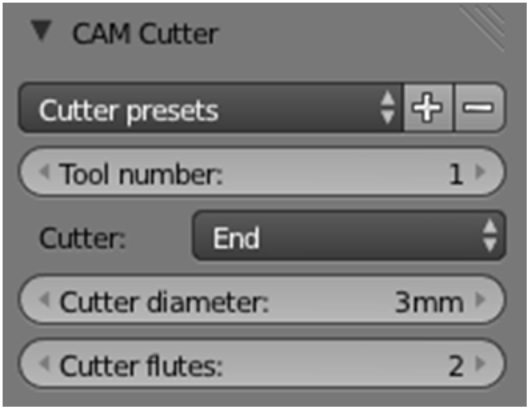
- Total number: Define the number of the tool
- Cutter diametter: Defines the dimeter of the tool, used for the path calculus
- Cutter Fluttes: this parameter only is used for the chipload calculation
CAM Machine
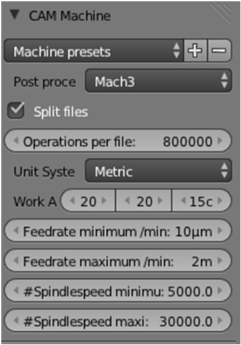
- Postprocesssor: Defiines the format of the output file. if the machne is not eady, the codes tht generate gcode are MACH3, ISO.
- Unit System. Metric or Imperial units system.
- Work area: here are defined the dimentions of the material that wil be roughed
- Feedrate min/max: It wil limit the given speed onthe advane panel.
CAM chains
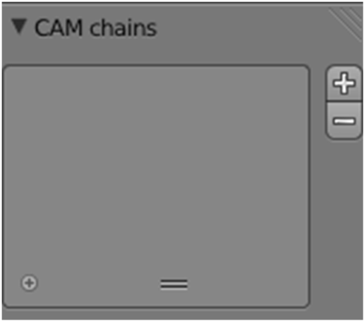
Is a tools that allows to chain operations like simulations, it means having a set of operations and execute them consecutively, is a very practical tool for code if you have automatic tool swapping.
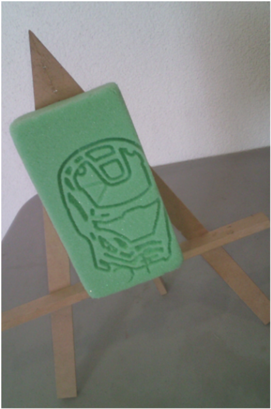
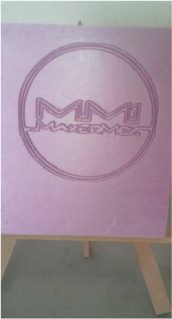
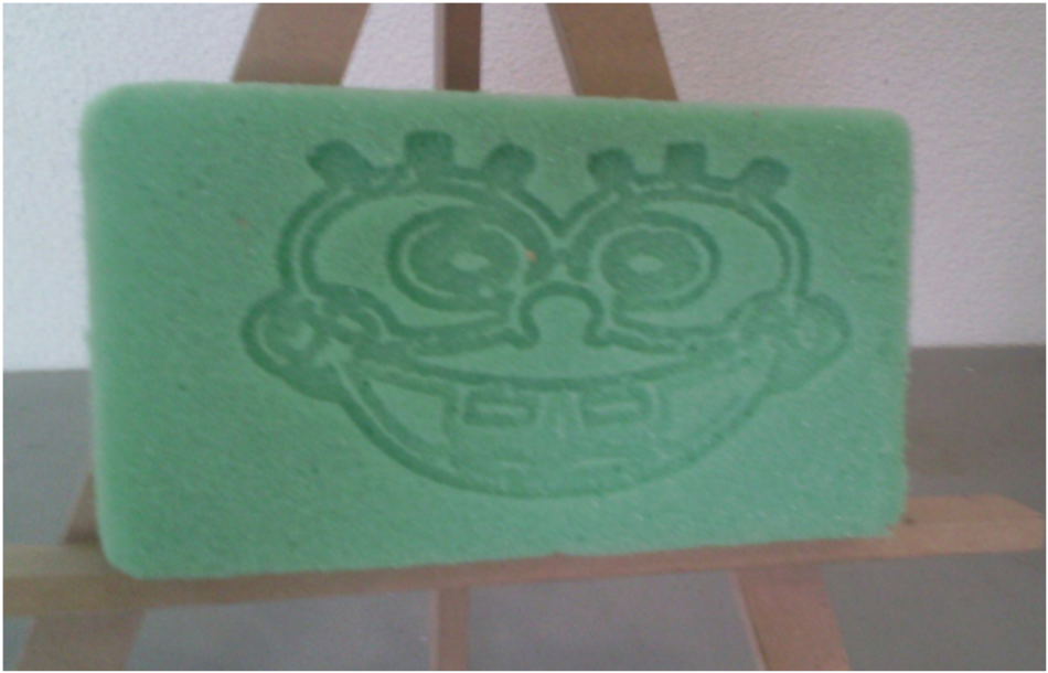
Now we will develop a cutout process that will generates an engraving of the surfaceof the material
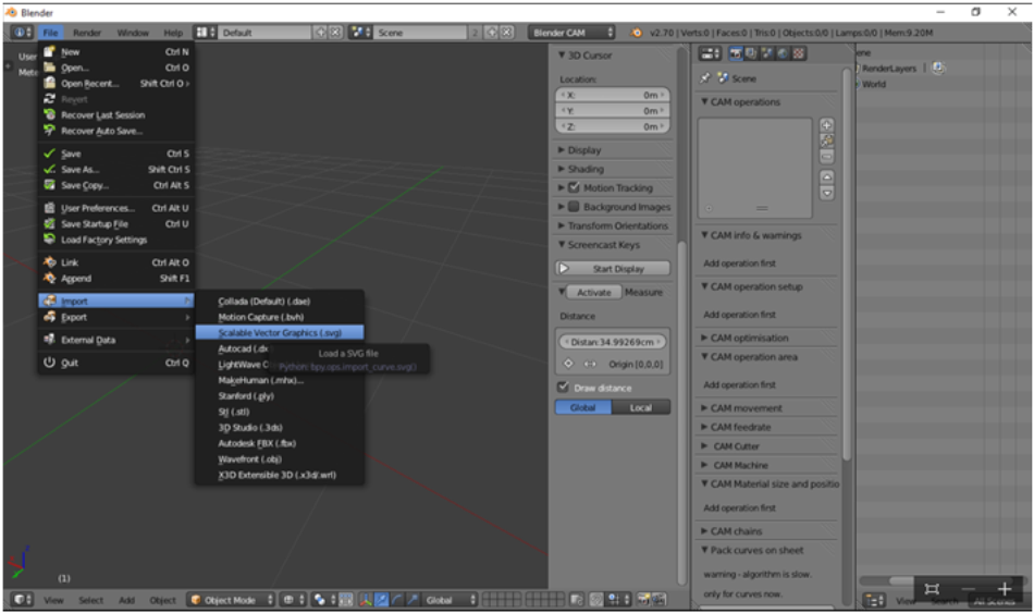
1.- Excecute BlenderCAM 2.- This time we import an .svg file
3.- In CAM operations Panel, selecct the object, in this cae curve and dd it to an operation. next give a name to the operation and file 4.- the parameters to use are the following
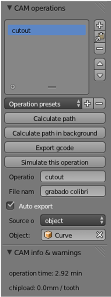
The name of the operation is cutout, this part, and the filename are optional, After setting this parameters we recommend to calculate the path, it will serve a simulation, if you eed to export gcode you need to calculate path.
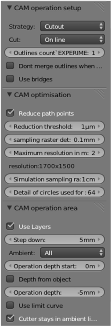
The action is cutout, this time the path will be over the line. we dont recommend the option “Dont merge outlies…” because it gives problems with blender. This part reduces the lines nmber as well as the reolution and simuation. the layer height is the same than the total roughing, generating a single pass. If we had needed two passes,the layer heigh must be 2.5mm, with a totaal roughingof mm, forthis material we wont have problem because we will rough a soft material.
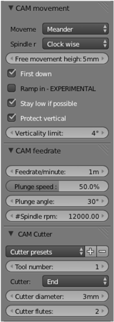
The type of movement used was mender because of the quantity of paths. One of the most important settings is the height of free movement. 5mm is an excelent value to enure that the module will not hit the material and the reult will be optimal
Is important to set the material area, in this case us 20 x 20 x 3 (cm). then, is importantto place the objectin the correct area. we can use “Position object”
To obtain the G code, click on export g code that is located in operations panel. This g code is generated into the Blender CAM installation folder . For the MM1 you have to open the gcode in notepad (or any plain text editor) and modify the following:
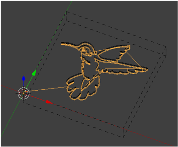
This is the main part of the g code of our hummingbird
| (GCode created using the HeeksCNC Mach3 post processor) (grabadocolibri.tap) (G-code generated with BlenderCAM and NC library) N10 G17 G21 G90 (Tool change) N20G43H1 N30T1 M06 N40 G00 X0 Y0 Z4.999 S12000 M03 N50 G00 X69.103 Y41.967 N60G01 Z-4.999 F500 N70G01 X68.746 Y42.554 F1000 N80G01 X68.41 Y43.15 N90G01 X68.102 Y43.737 N100G01 X67.831 Y44.302 N110G01 X67.606 Y44.829 N120G01 X67.435 Y45.303 |
CCheck the number of line (N100). When we will add an instruccion, this one have to be correctly numbered, in this BlenderCam generated gcode the number have increase by ten.
Example 1:
| N100 (gcode generated by BlenderCAM ) N101(Added code) N102 (added code 2) |
Example 2
| N98 (added code) N99 (added code 2) N100 (code generted by BlenderCAM) |
After the instruction (N30T1 M06) add the following:
| N31 G28 (This instruction sed all the axis to home) N32 G4 S3 (this instruction waits 3 secons to enable the comunication) N33 M280 P2 S10 (this instructin turns off tthe motor, must turn on before turning on, not to change) N34 G4 S3 N35 M280 P2 S90 (this instruction turn the motor on with a speed of 90 rev/s, needed to form the material) N36 G4 S3 |
This is the final part of our hummingbird
| N100940G01 X62.35 Y135.168 N100950G01 X62.303 Y135.147 N100960G01 X62.259 Y135.122 N100970G01 X62.218 Y135.095 N100980 G00 Z4.999 N100990 M02 |
Before the M02 instruction the following wil be added:
| N1009801 G4 S3 N1009802 M280 P2 S80 N1009803 G4 S3 N1009804 M280 P2 S60 N1009805 G4 S3 |
The modified cde is as follows:
| Start (GCode created using the HeeksCNC Mach3 post processor) (grabadocolibri.tap) (G-code generated with BlenderCAM and NC library) N10 G17 G21 G90 (Tool change) N20G43H1 N30T1 M06 N31 G28 N32 G4 S3 N33 M280 P2 S10 N34 G4 S3 N35 M280 P2 S90 N36 G4 S3 N40 G00 X0 Y0 Z4.999 S12000 M03 N50 G00 X69.103 Y41.967 N60G01 Z-4.999 F500 |
Final
| N100960G01 X62.259 Y135.122 N100970G01 X62.218 Y135.095 N100980 G00 Z4.999 N1009801 G4 S3 N1009802 M280 P2 S80 N1009803 G4 S3 N1009804 M280 P2 S60 N1009805 G4 S3 N100990 M02 |
After the modifications to the Gcode we save it as .gcode all the files that the printer can read. If we want to load the gcode from pronterface we have todownload the following version: https://github.com/kliment/Printrun , if not, simply save the gcode in the SD card and load it to the MM1
PASTE MODULE
In this section of the manual, e will talk about a very exciting module, de paste module, this is an experimental module to work with any pasty material,; from clay, to chocolate.
Note
An important thing is that this module only works with cold paste.
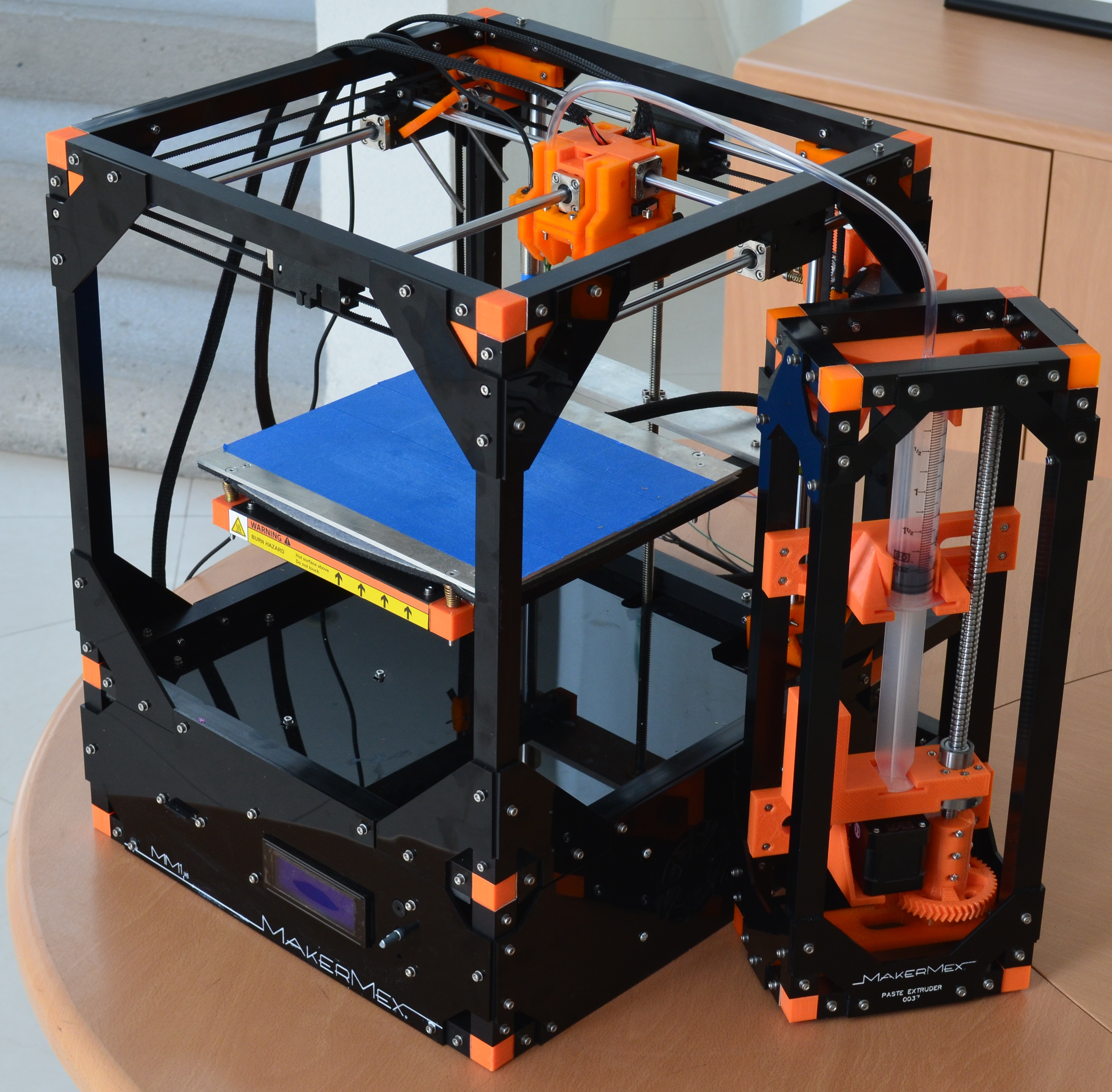
General
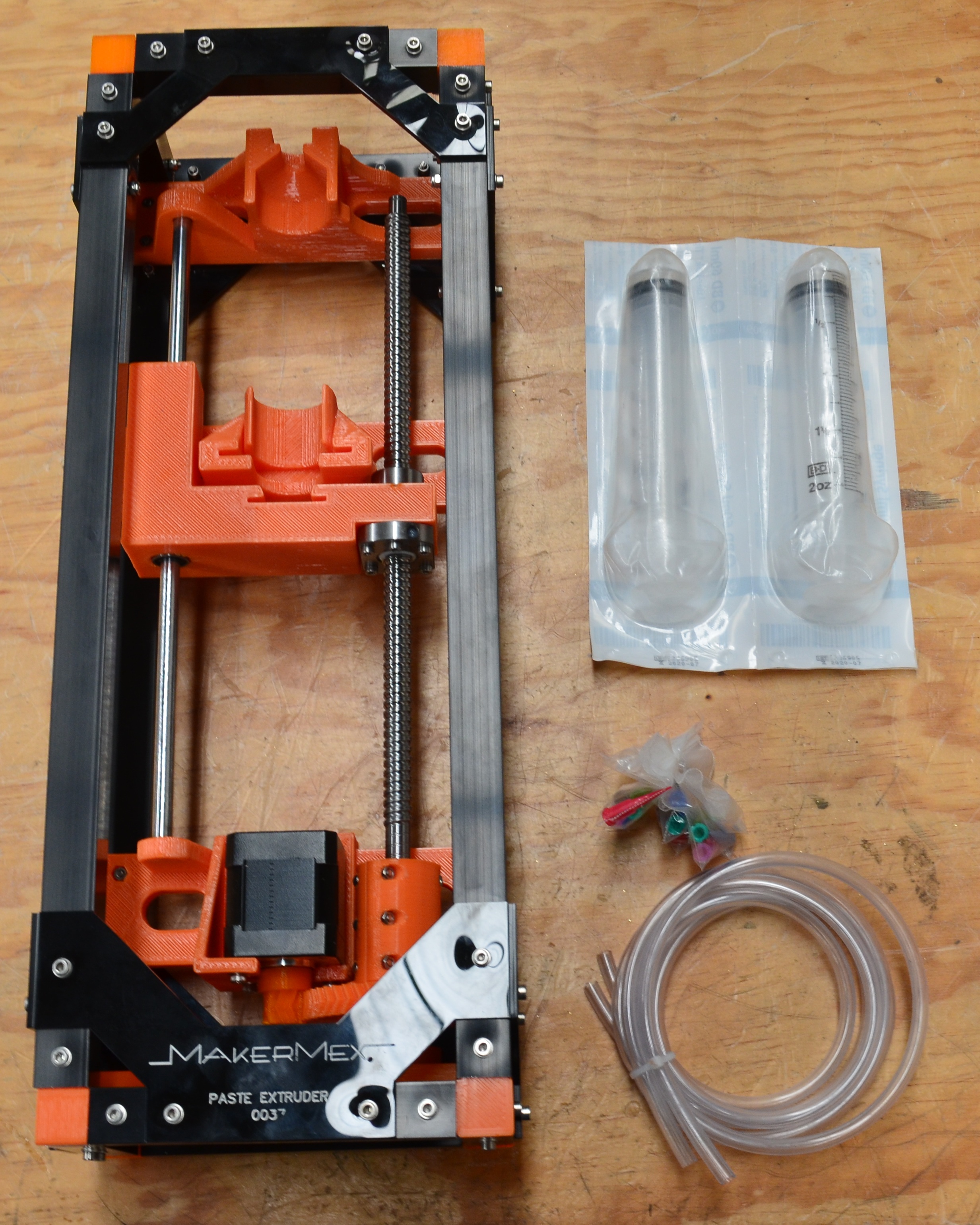
First, we will identify the comonents of our pastemodule, it is divided in two parts; the pumping station and the head. it also contains some accesories for the pasta injection.
The paste module contains the following
| 1 Pumping station + motor cable |
Pumping staton and accesories
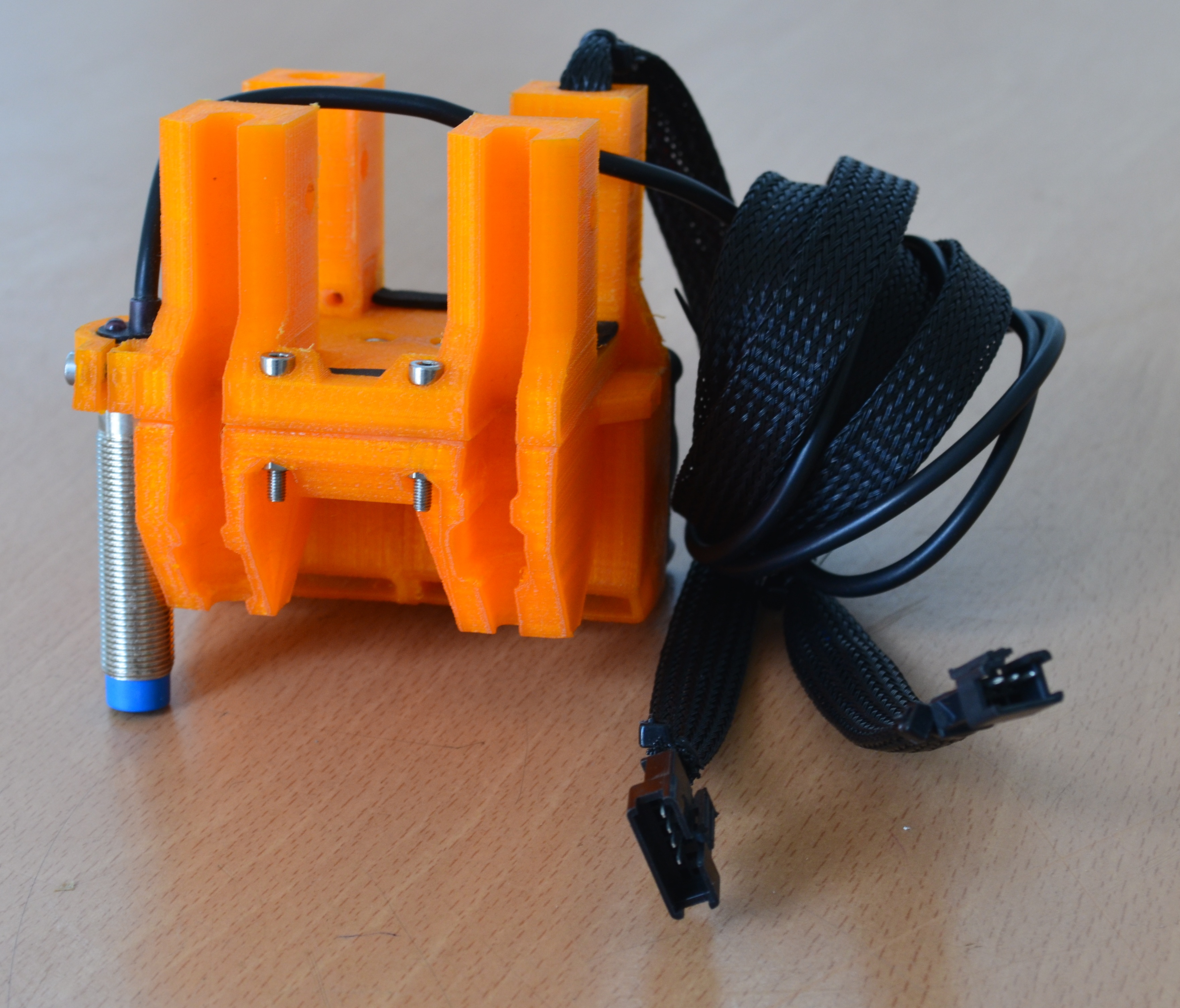
Printing header
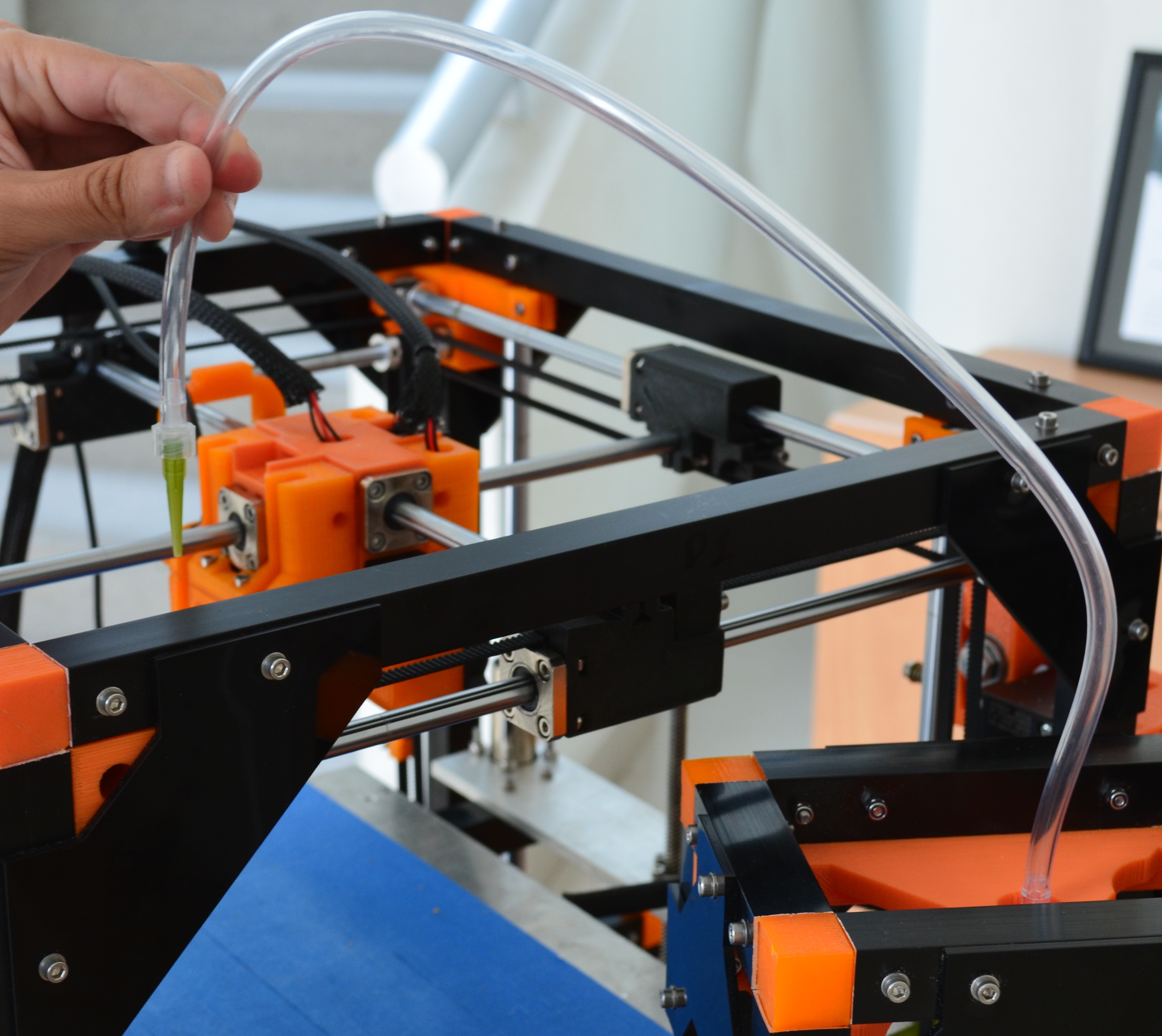
Now, we are going to begin, but first lets prepare the components that will hel us to print.
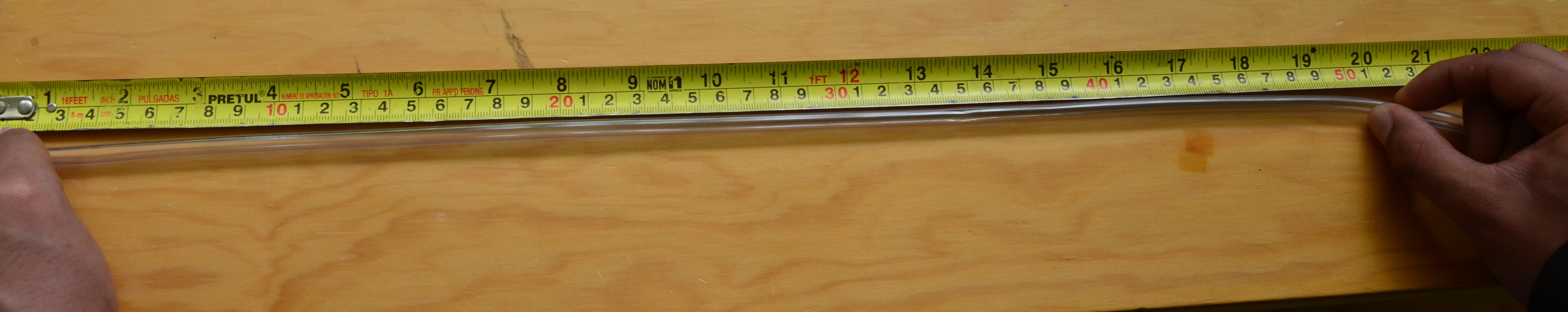
Step 1
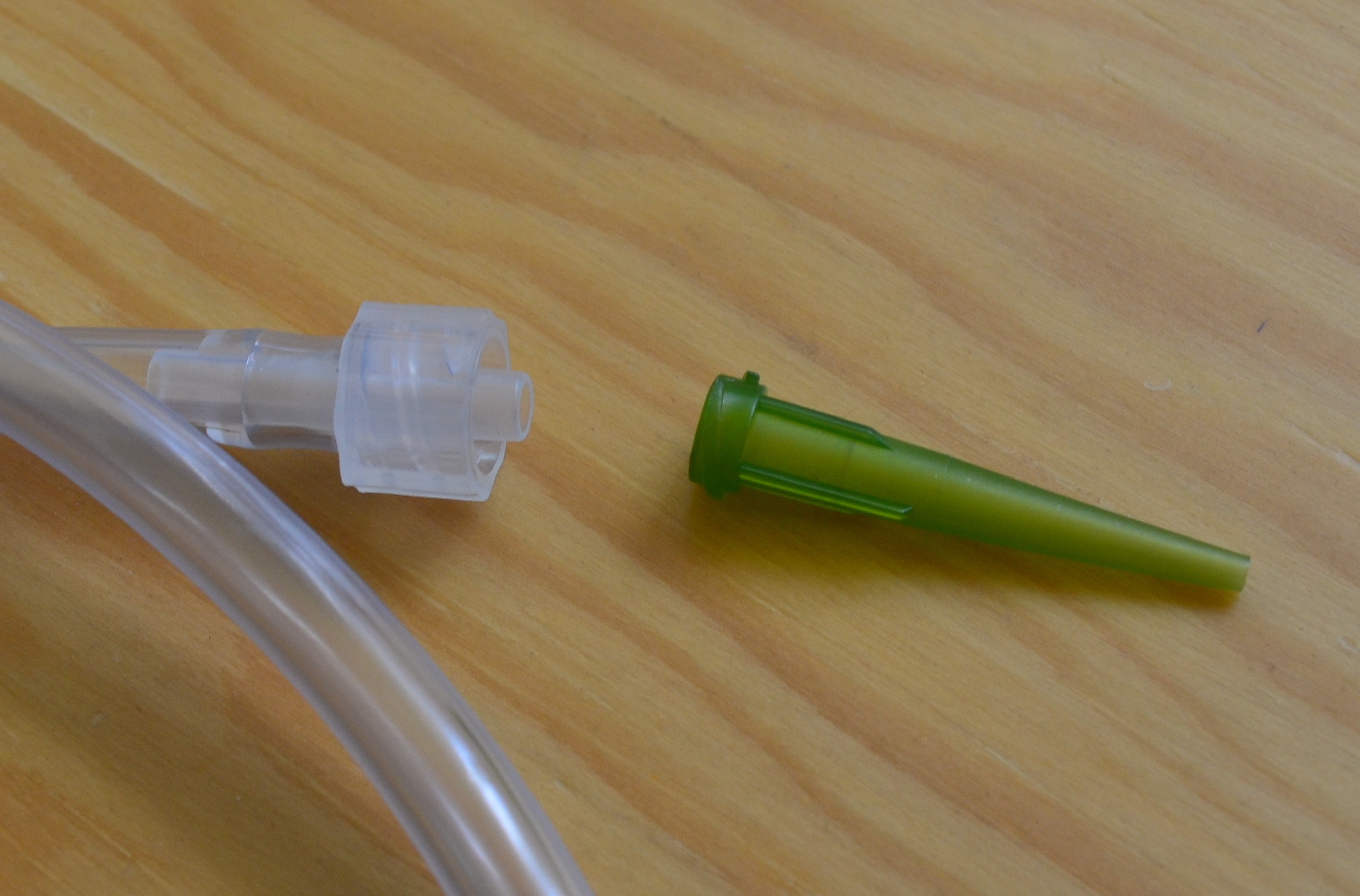
Cut a level tube of 50 cm long
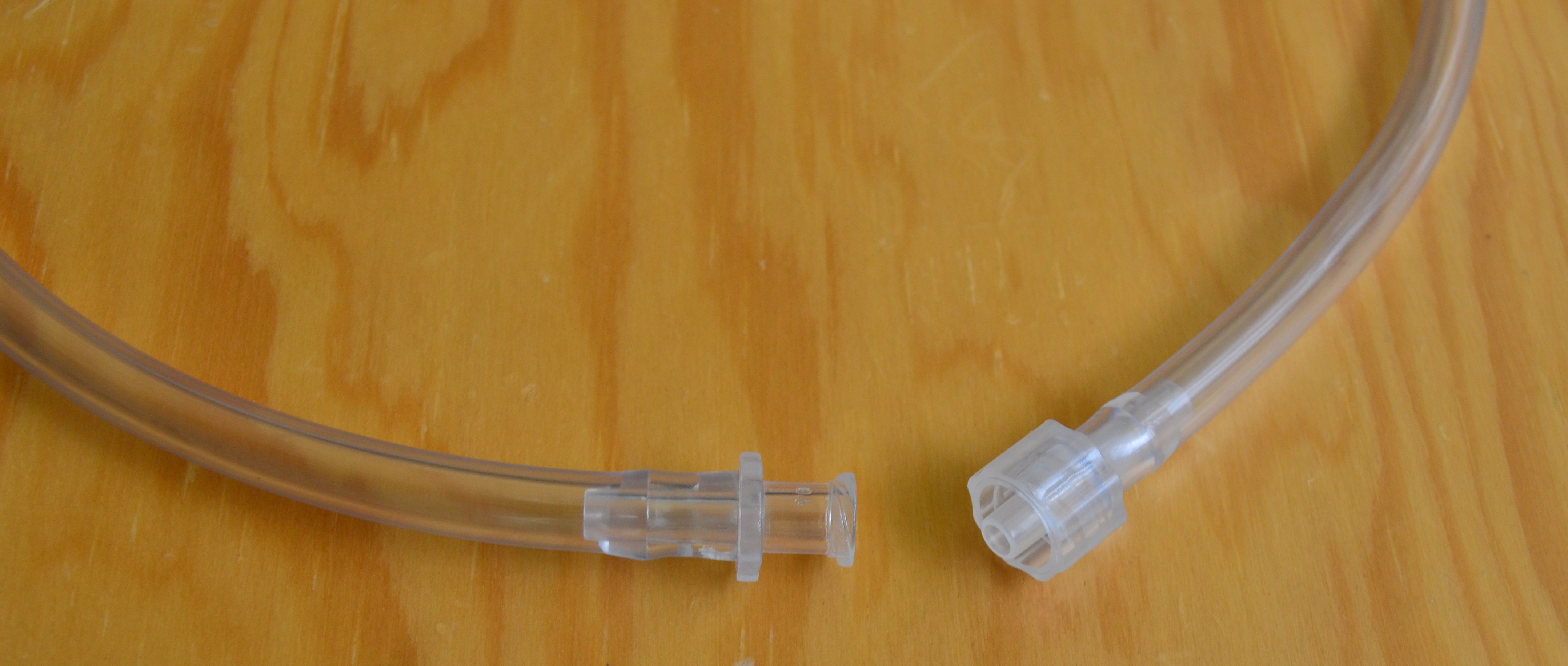
Step 2
Put a female leuer clock in one edge and a male luer clock in the other.
Female luer clock
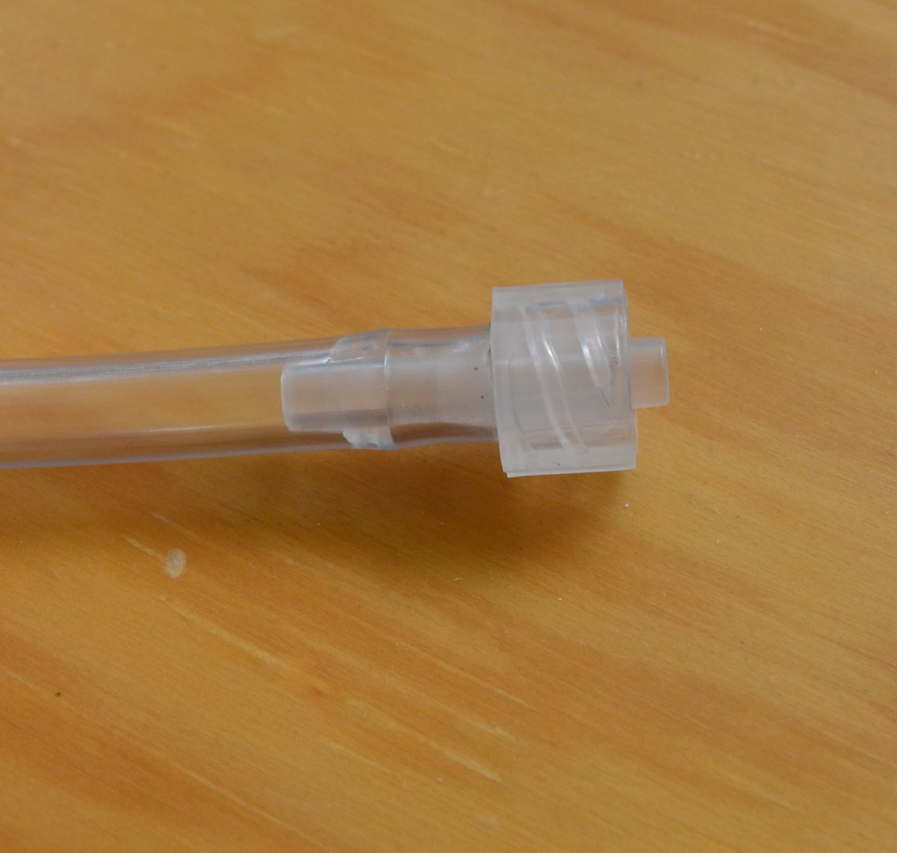
Male uer clock
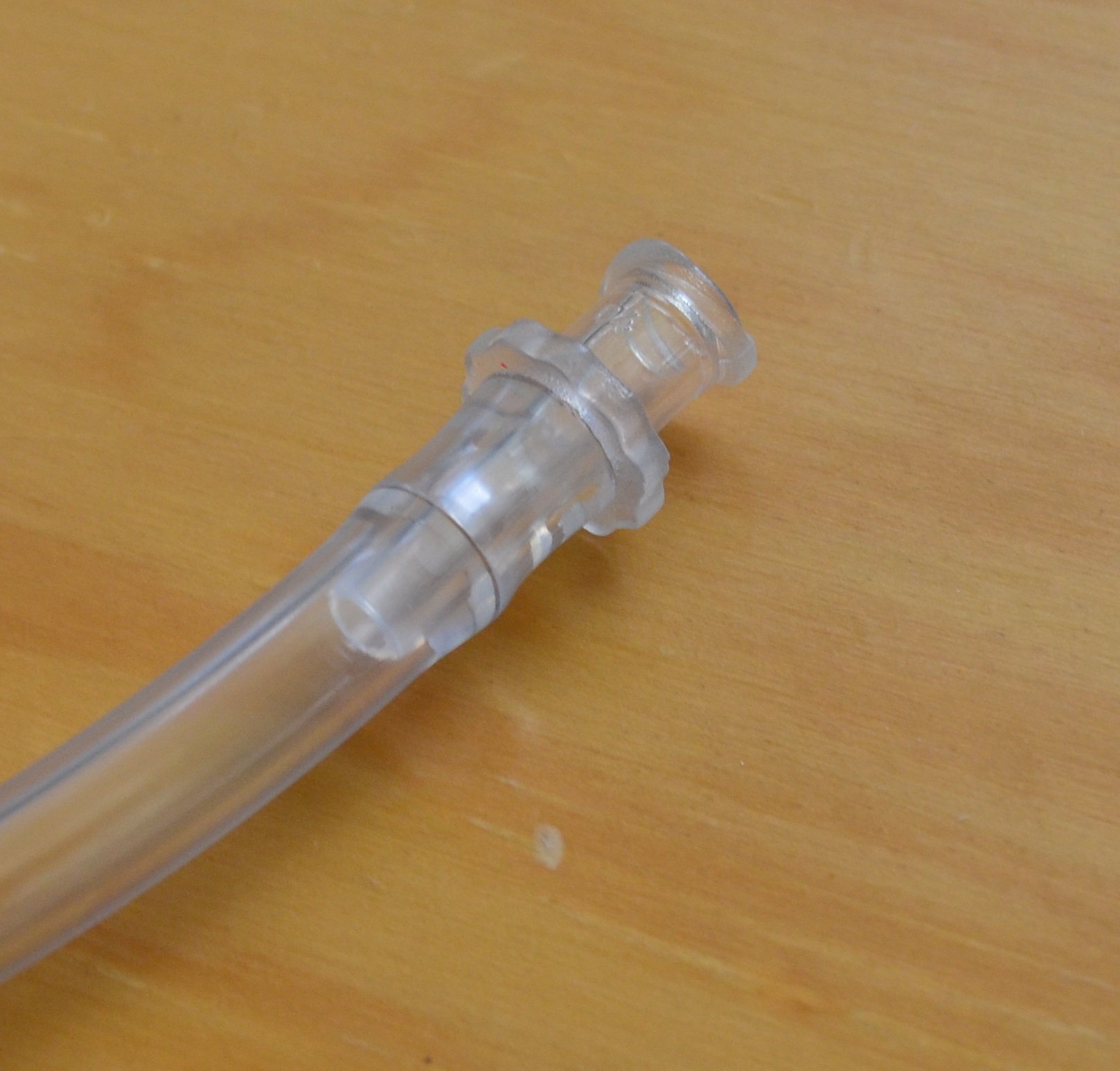
Must result this way, it will be the leveling tube of our module.
Step 3
For ths ste we need a syringe, mount it in the pumping station, also put the tub in the syringe and the noozle
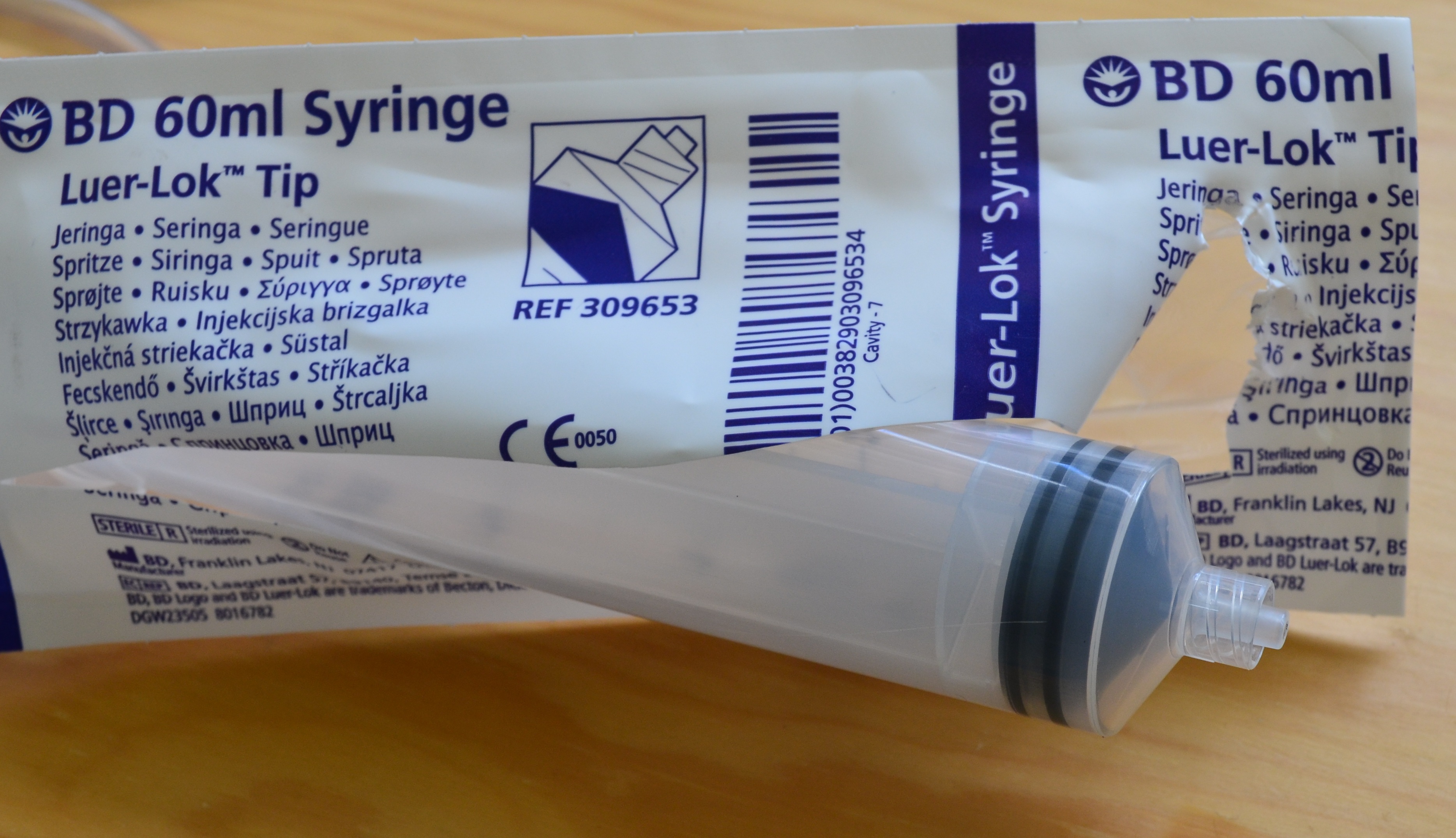
Open the syringe ackage and look how to put the male luer clock. you have to screw the luer clock or the noozle to hold them.
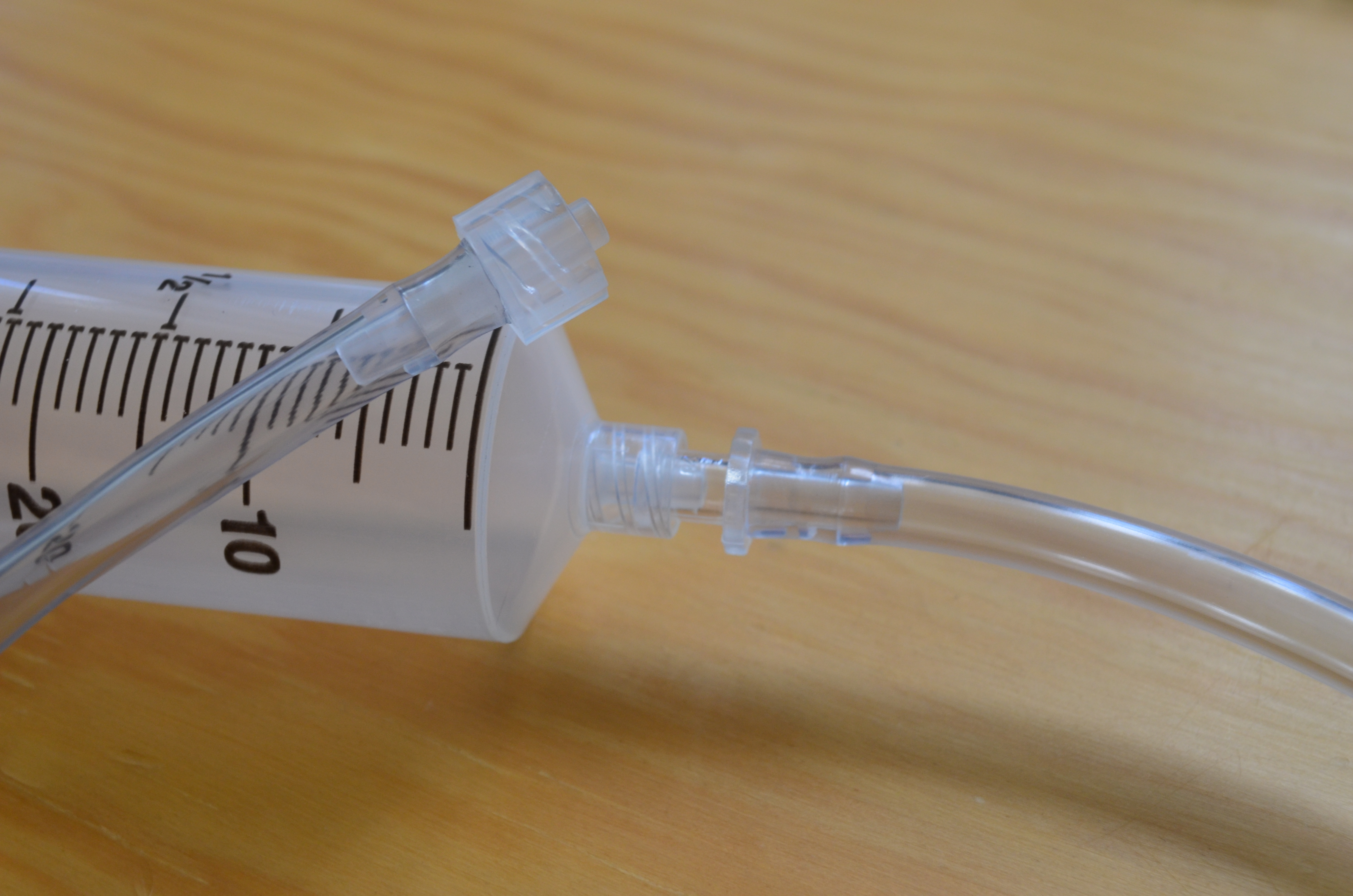
Once you have installed the tube and the noozl in the syringe, you change fro one noozle to other when needed. Now lets install the noozle in the pumping sttion, whe have to ensure that the syringe is firmly hold to the central part to the plunger.
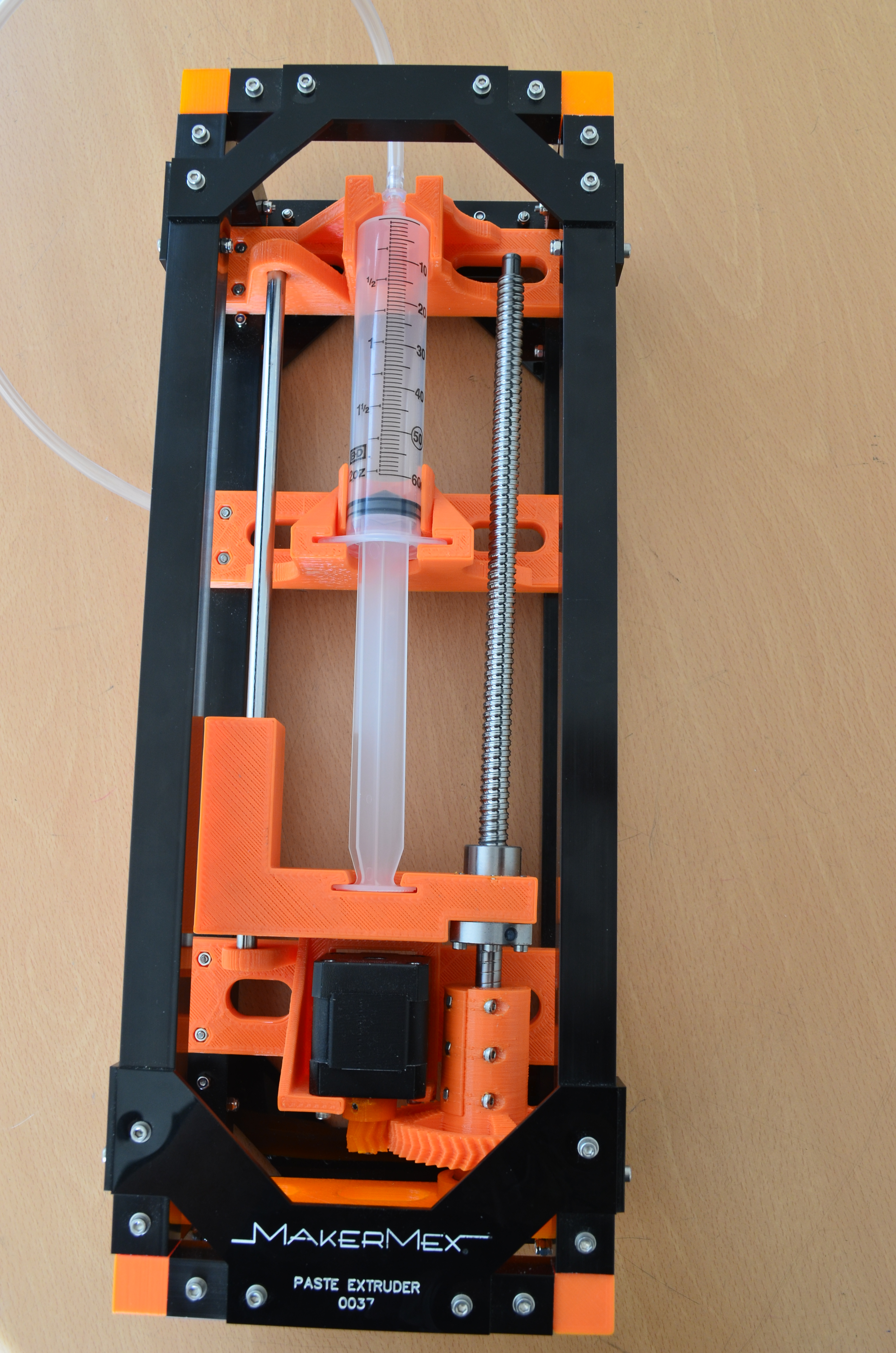
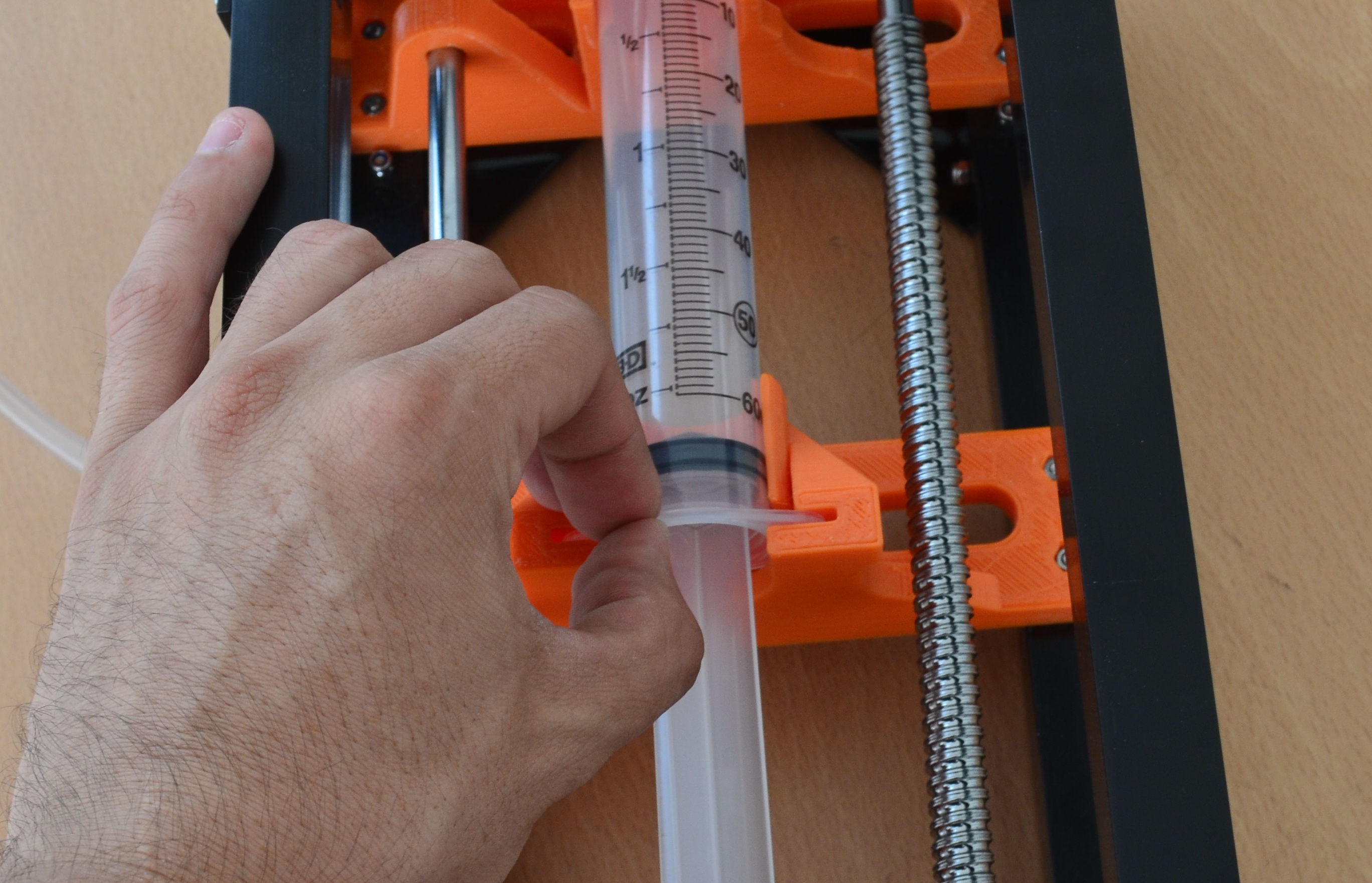
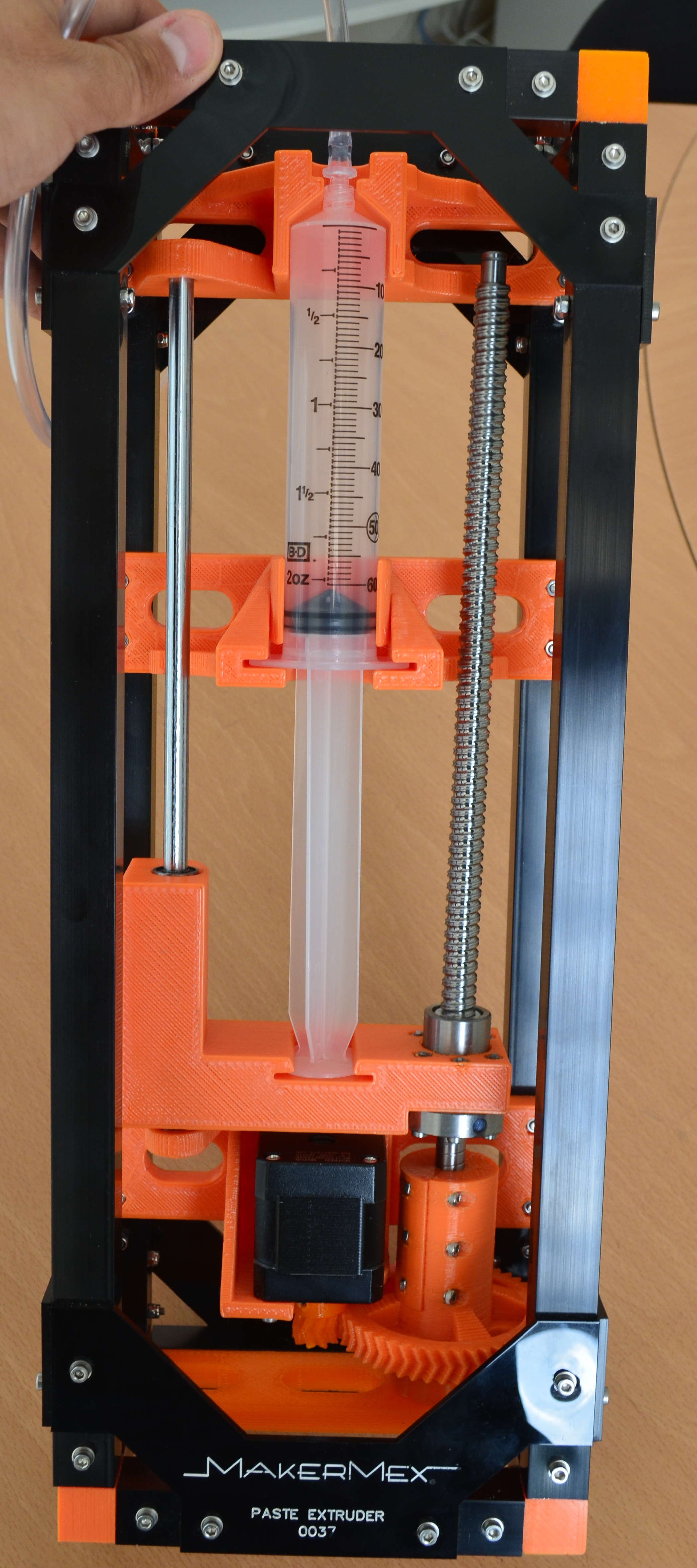
This is how the syringe must be installed in the pumping station
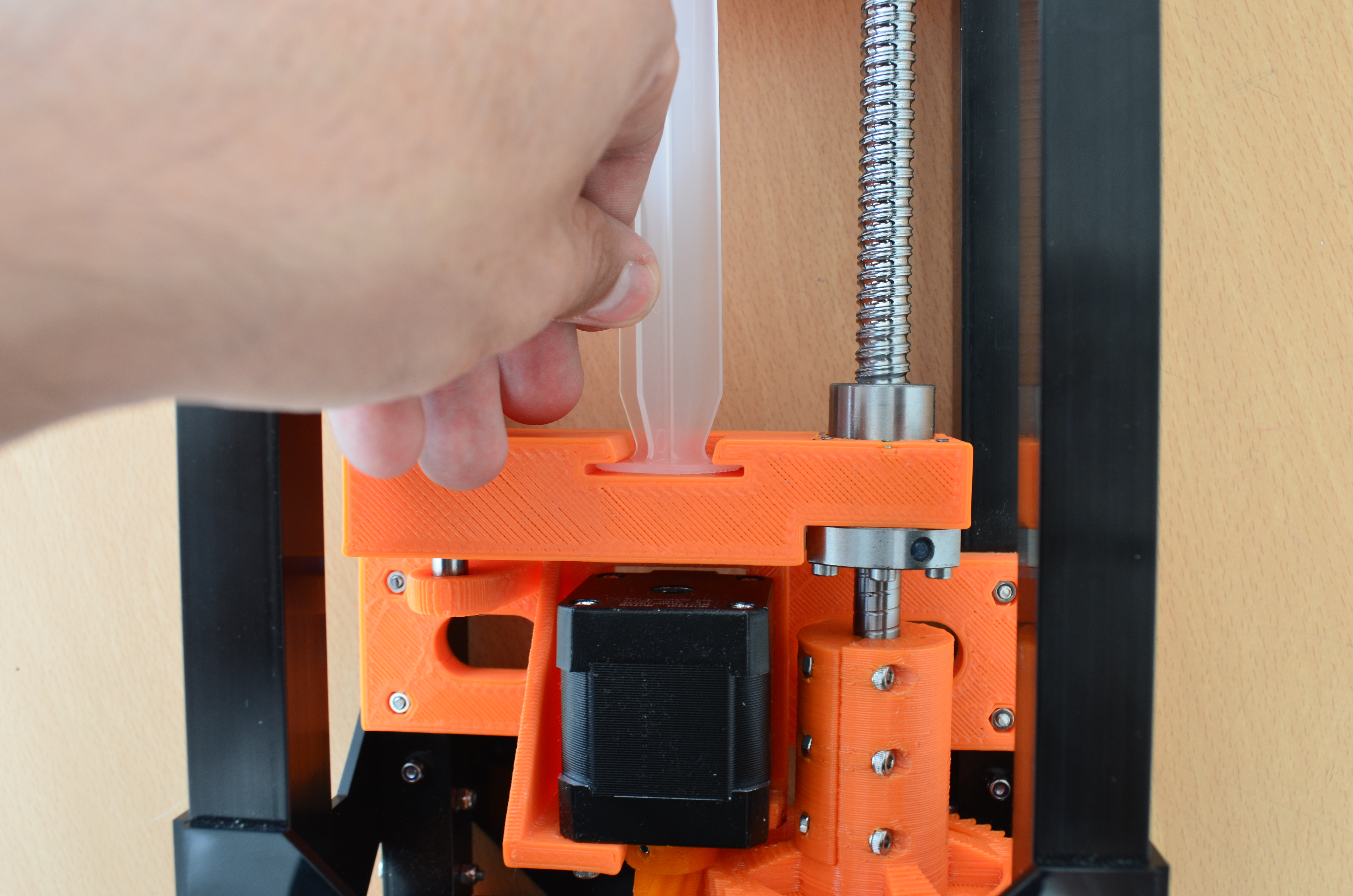
Note
if the base that is attached too the threaded rod is too high you must move it down so you can instak the syringe, this is simple, only turn the big gear counter clock, and thn you can put the plunger of the syringe in the hole of the plastic base.
To end this steo you have to conecct the motor of the pumping station.
Step 4
Lets put the paste module on the printer, for this step uninstall th module that is installed, remember that to uninstalla module you have to remove the holding clip.
Mount the header as shown in the images and put the holding clip.
Step 5
Now you have to plug the connectors,in this module you only cnect two wires and the dua etrusion clock, remeber that the wire must pass over the top profiles.
Note
From the 3D printer with serial number 198 and above, dual extrusion tumbler is not necessary for the machine or any module, and is not included, this feature is now included in the controller firmware; if the serial number of your machine is lower than 198 and you want to update the firmware please contact our support team via the forum .
Step 6
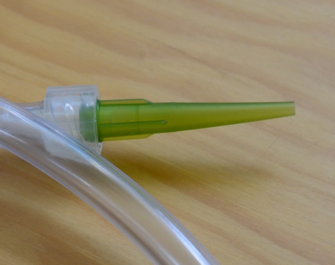
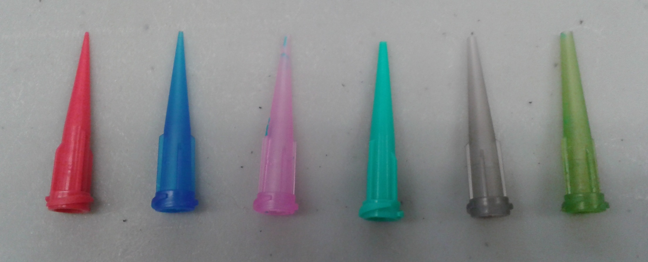
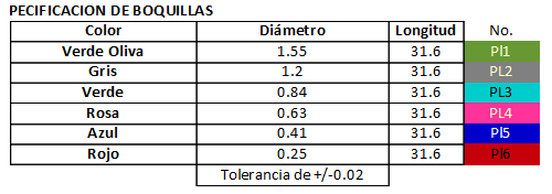
With all conected, lets put the nooles, each slot is for a type of noozle, it is posible to use two types of noozle.
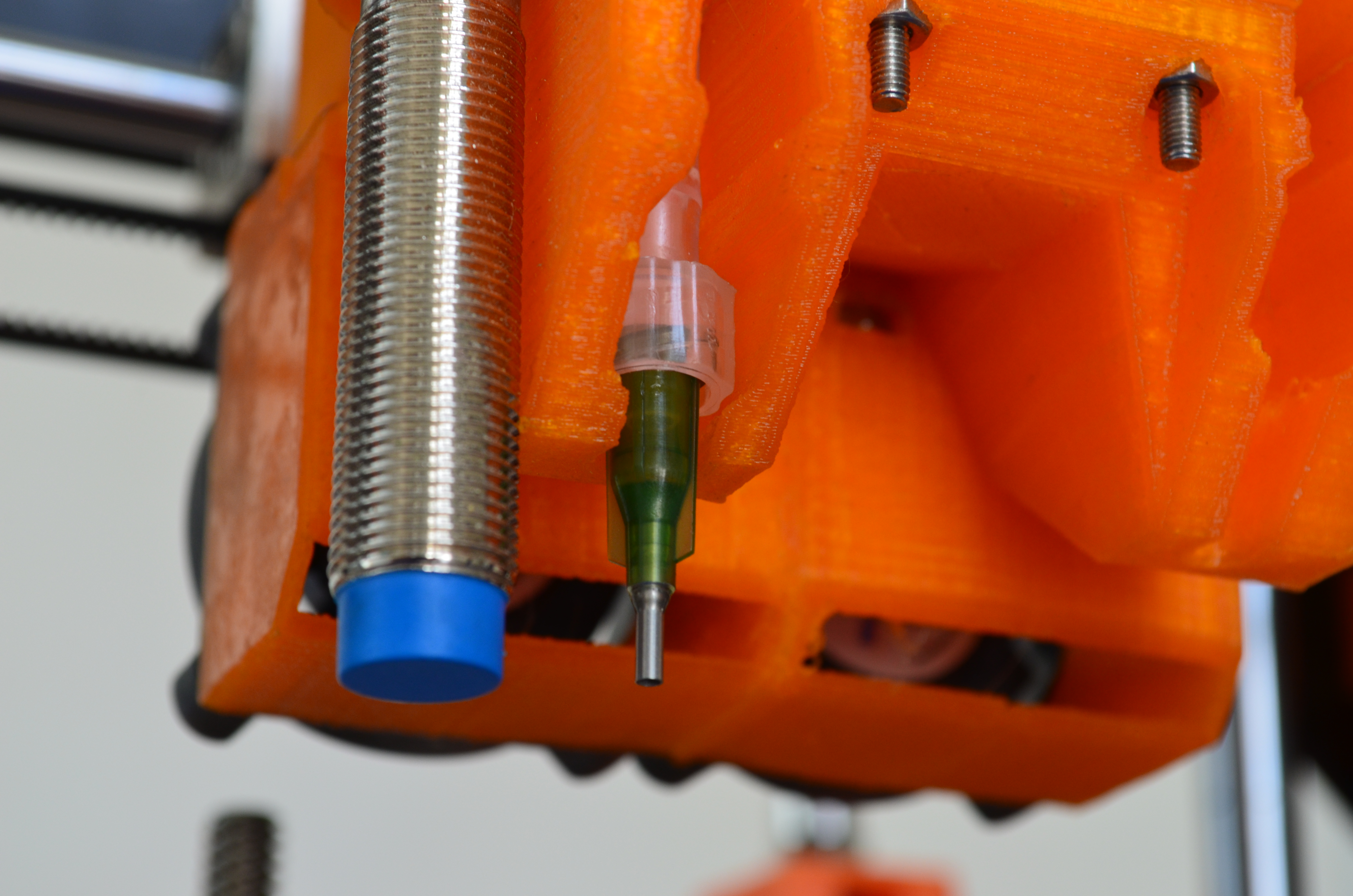
Lets install the plastic noozle.
It must be installed in the right side of the module, looking it front.
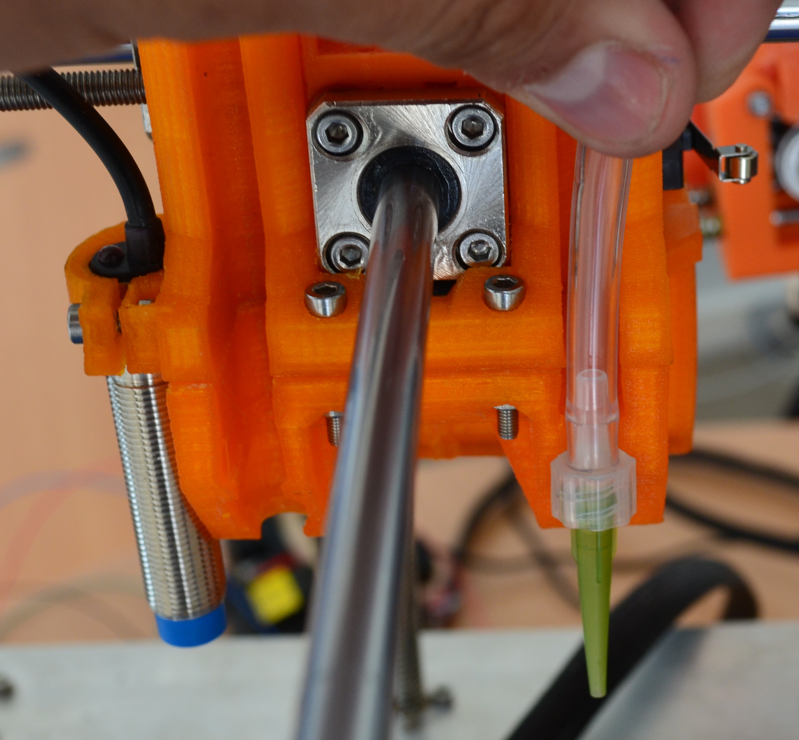
Push until the noozle reaches the bottom of the sace as shown in the image
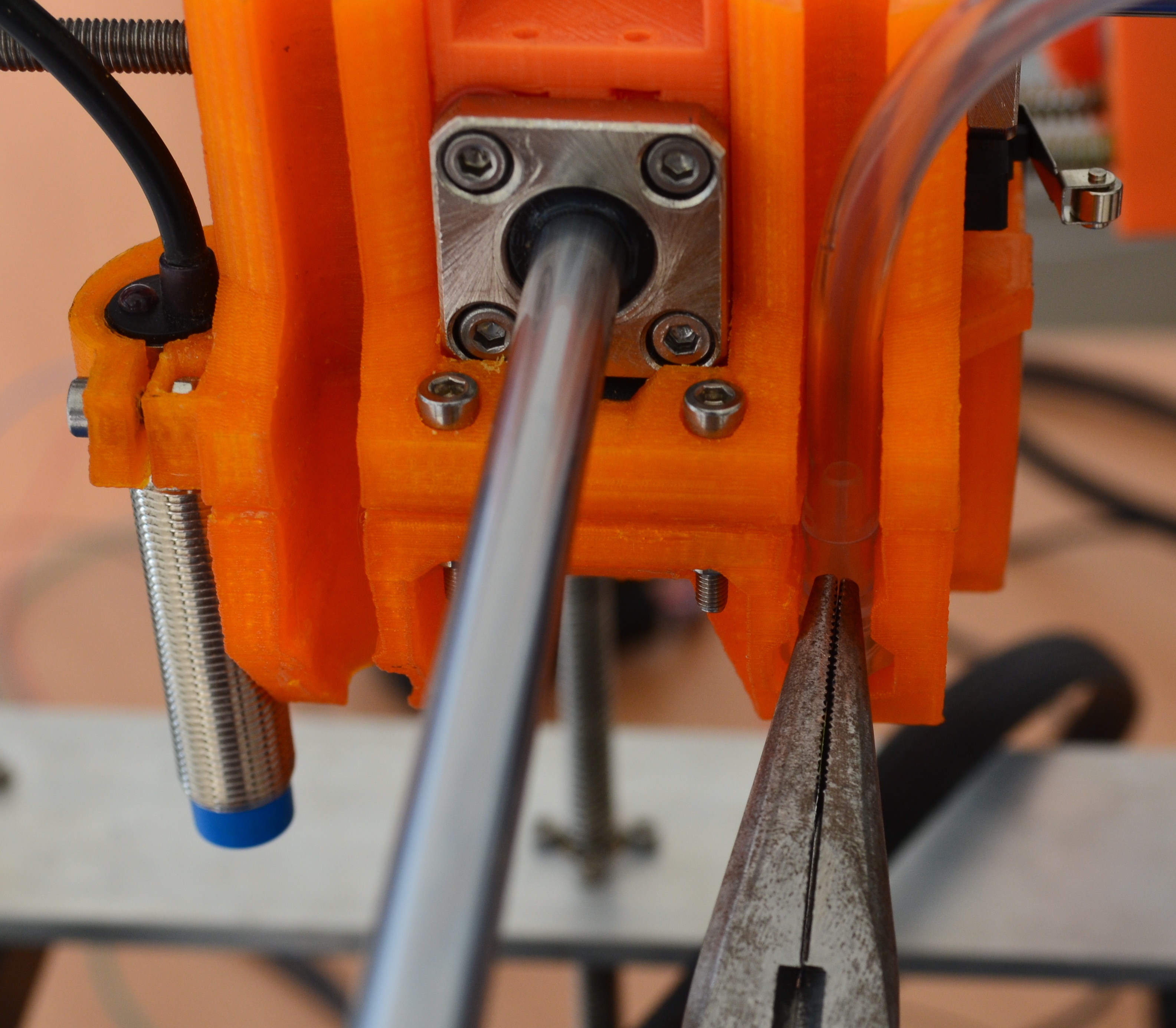
Now we wil put the noozle thaat has the metal tip, this noozle goes to the left side of the header as shown in the image, also use pliers to push it to the bottom.
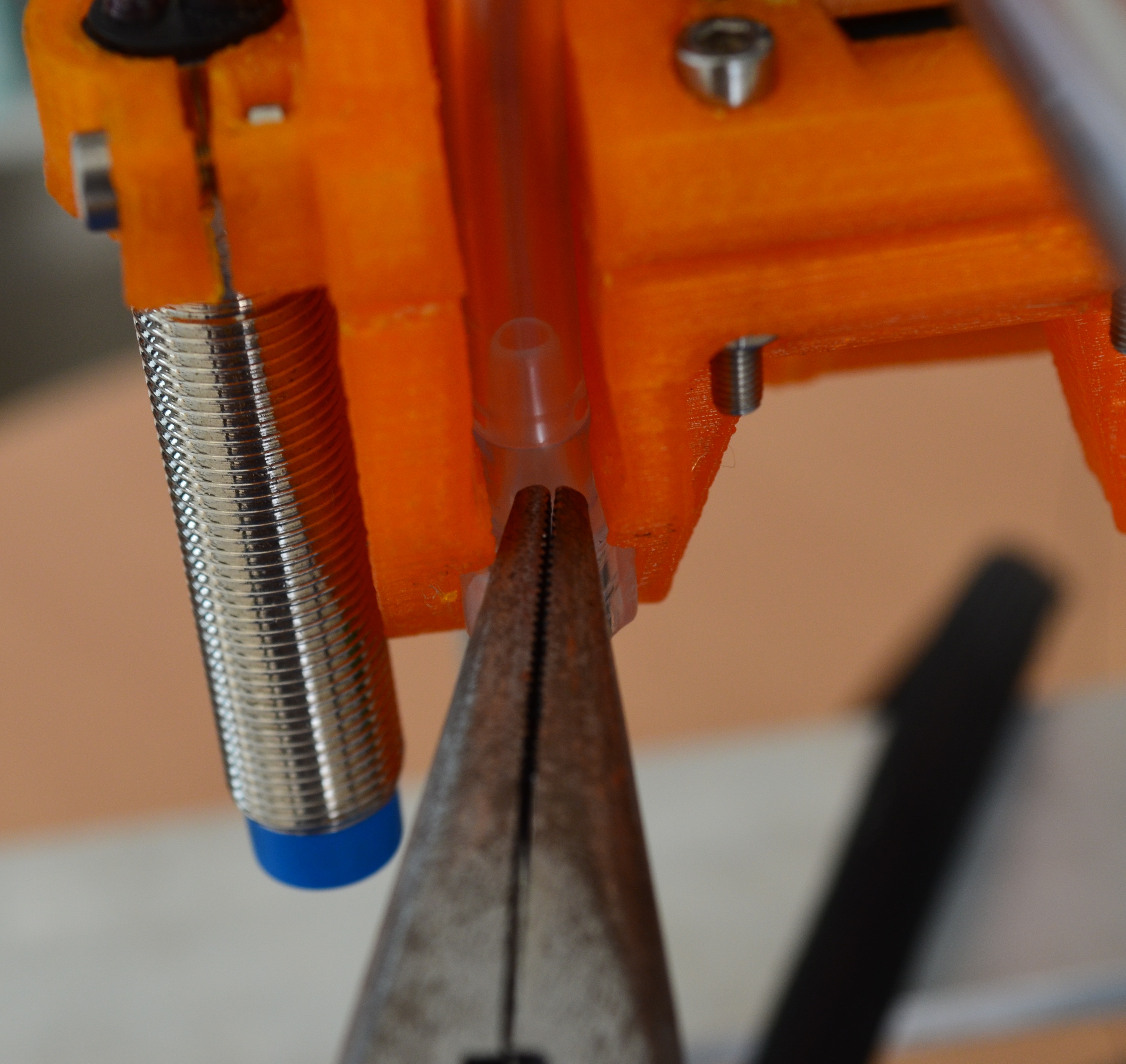
The same as with the other noozle, thi one has to enter in the available slot.
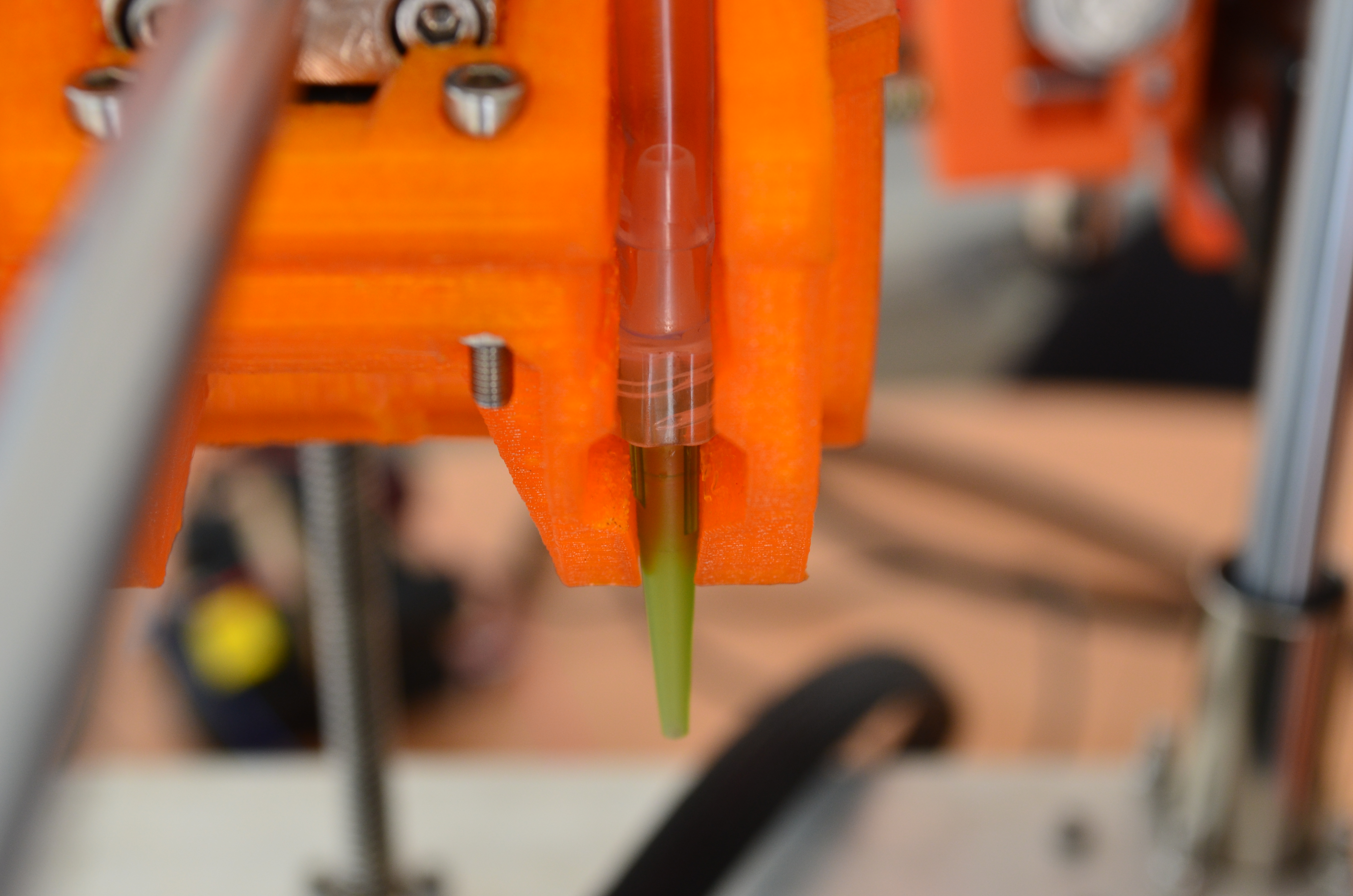
Our paste module must look as in the picture.
Step 7
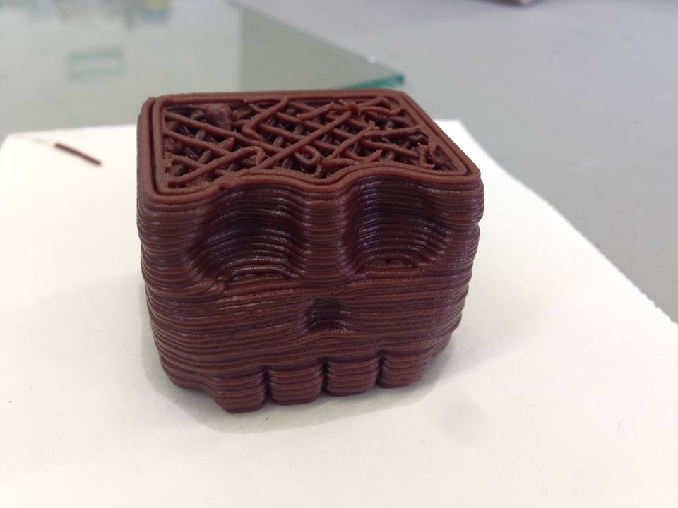
Now we will show you some cura parameters to do your tests. in thi example we will tell you how to mix nutella to print with chocolate.
ingredients: Nutella, Glucose (you can buy it in raw materials for pastry shops).
Tip
Have in hand mesauring instruments for grames and mililitres.
Paste prearation;
Ingredients:
| -120gr of nutella. -10.6gr of glucose |
put the ingredients in a bowl, mix it until the mix has a hahrder consistency than nutella, ensure the correct disolution of the glucose.
When the paste is ready put t in the syrnge, is recommended to remove the plunger of the syringe an mantain the tip of the syringe in a vertia position so you can fill it with the pasta, avoid buubles, you caan break the buuble twisting the syringe with your hands s if t was a roller.
You can reet that step the times you need to get all the buubles out, also you can hit the body of the syringe with a spoon to get the air out.
When there are no bubles put the tube and press so the pasta begin to move inside the tube and comes out of the noozle. ensure you use the correct parameters and noozle sizes.
The speed depends on the vicosity of the pasta, low speeds are recomended, between 10mm/s to 25mm/s
We can experiment with many tyoes of cold pastes, like nutella and glucose, sugar and lemon, fondant, clay, silice, play-doh, whipped cream. the important thing is the viscosity, it must be like toopaste. You can try the viscosity putting a line over another with the syringe; the bottom one must support the other
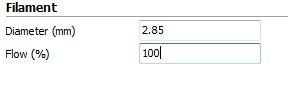
Paraeters used to print
Basic
| Layer heigh .8 Shell thickness 2.4 Retraction no Bottom/top thickness 2 Fill density 30 Print speed 15 Temperature 0 Hot bed 0 Support none Platform adhesion type none Diameter 3 Flow 7 |
Advanced
| Nozzle size 1.2 Intal layer thickness .8 Intal layer line width 100 Cut of object bottom 0 Dual extrusion overlap .15 Travel speed 15 Bottom layer speed 15 Infill speed 0 Outer shell speed 0 Inner shell speed 0 Enable cooling fan. Si |
Thi must be the result
Frequent problems
How to clear a noozle jam
Step 1
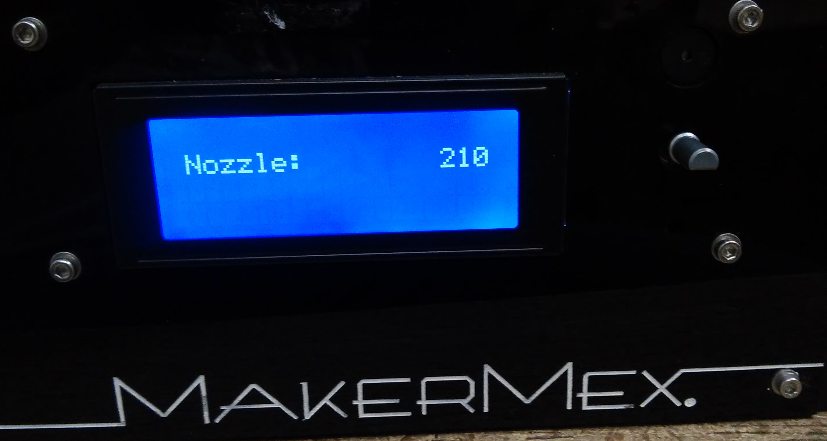
Lets lean the filament out of the nnoozle, remember to heat up the noozle before removing it, adjust the temperature depending on the filament material, in this case we havea PLA jam, so, heat u to 210°C so the material can be unloaded.
In the the LCD control go to Control -> Temperature -> Noozle, and move it up to 210°C and click.
When the noozle reaches the temperature we can remove the filament.
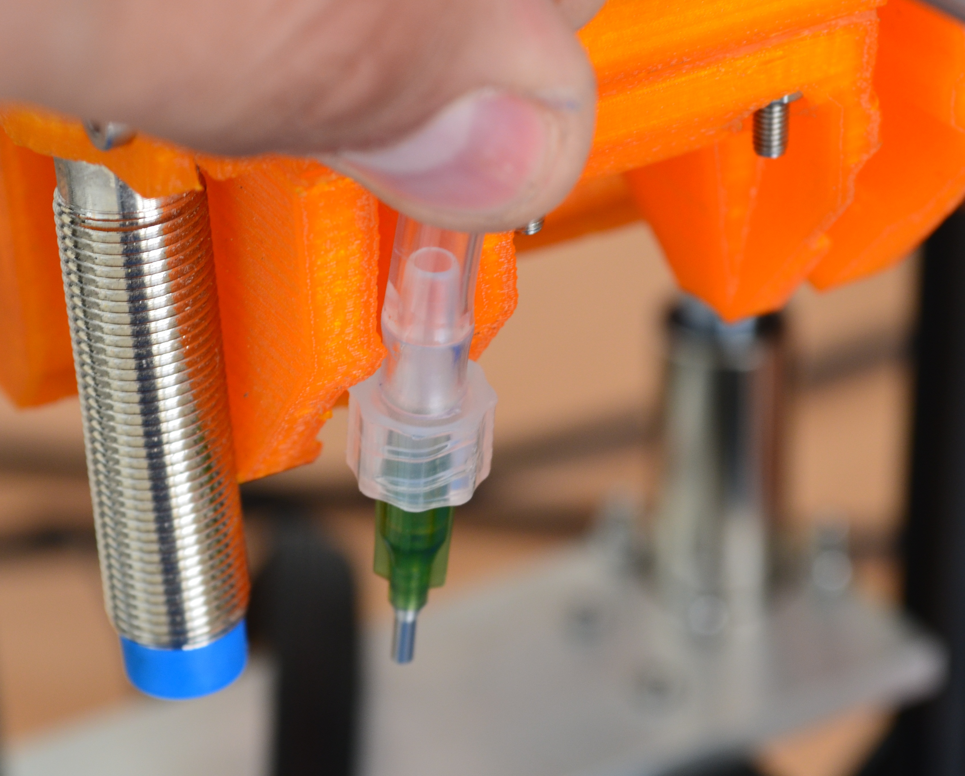
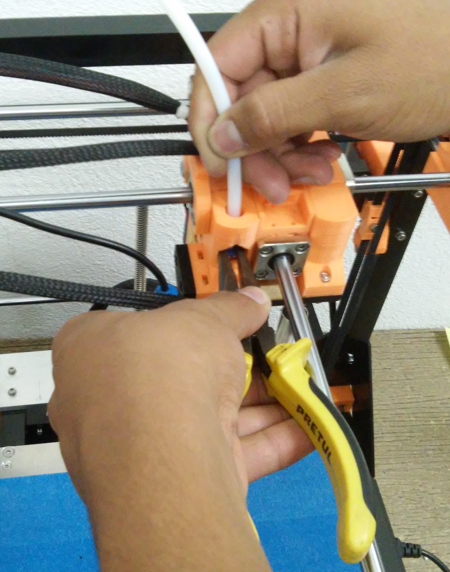
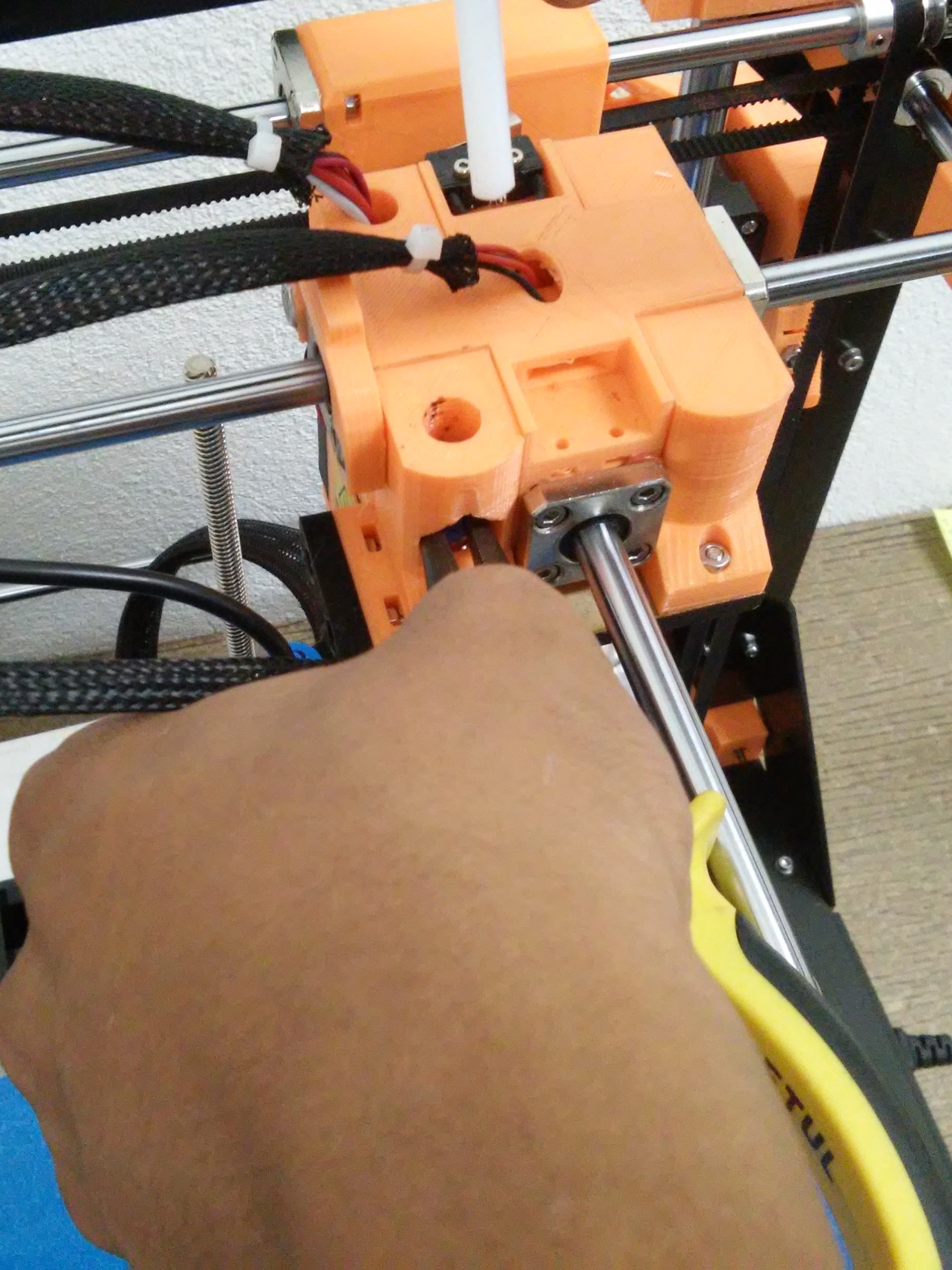
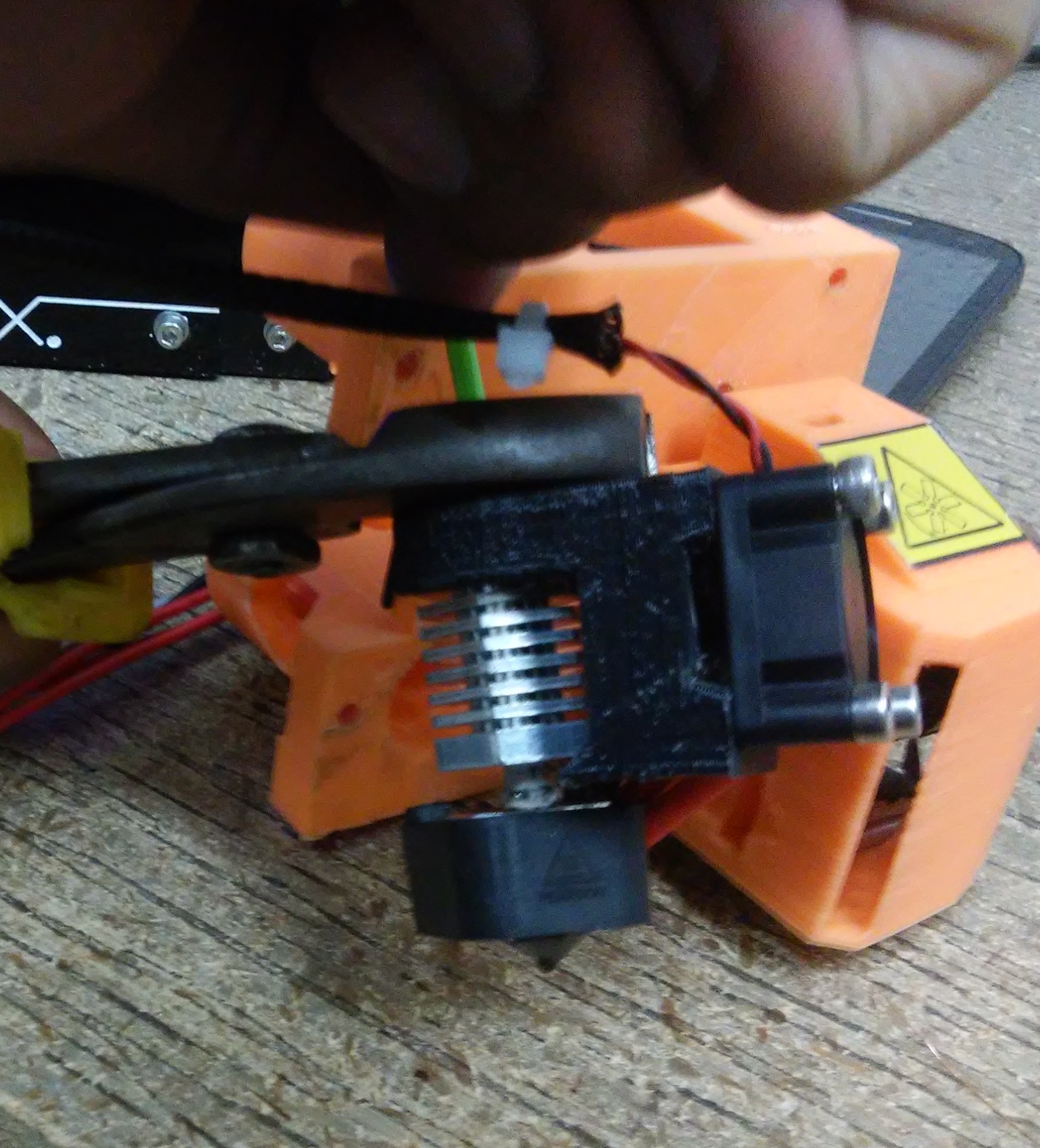
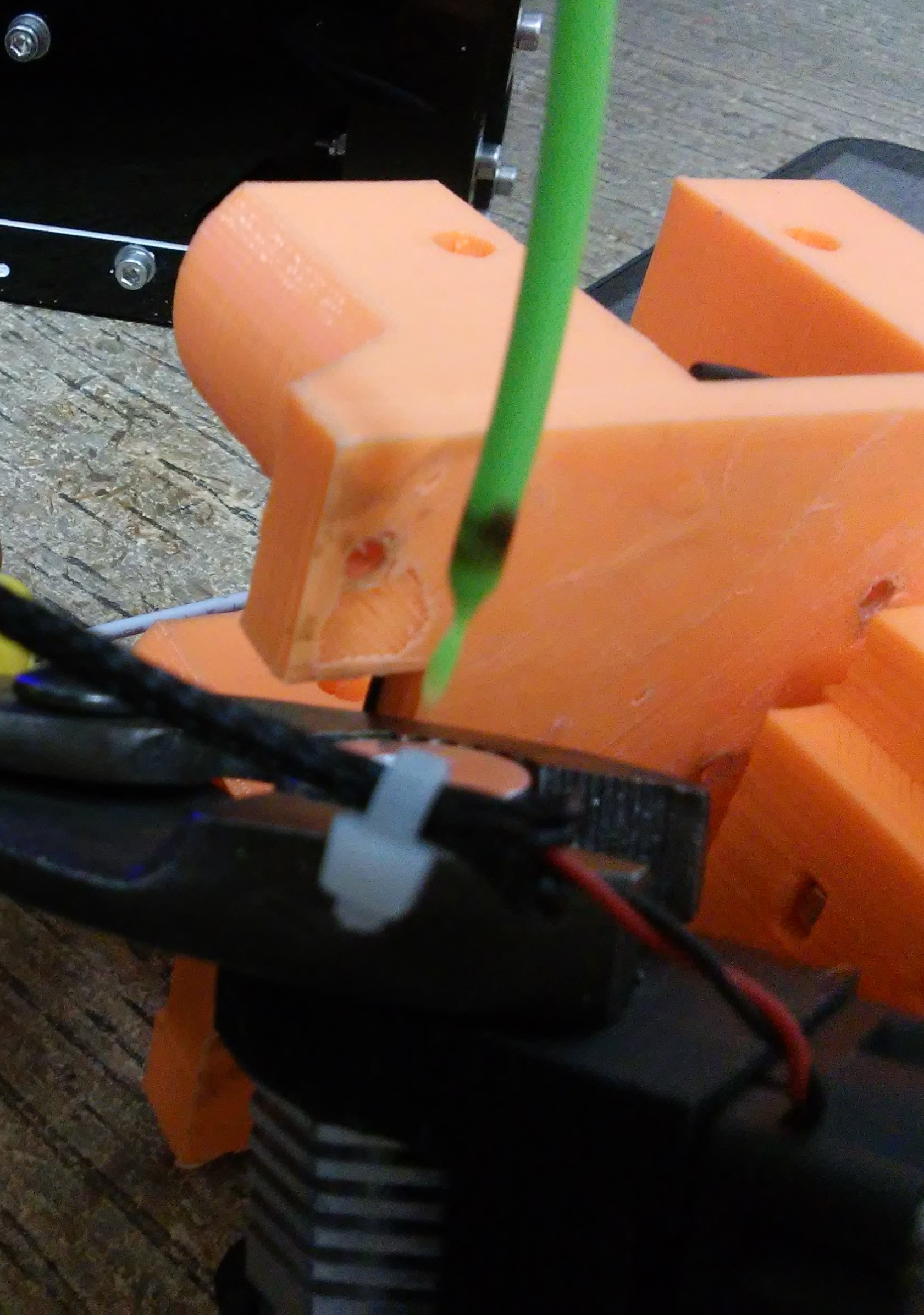
Step 2
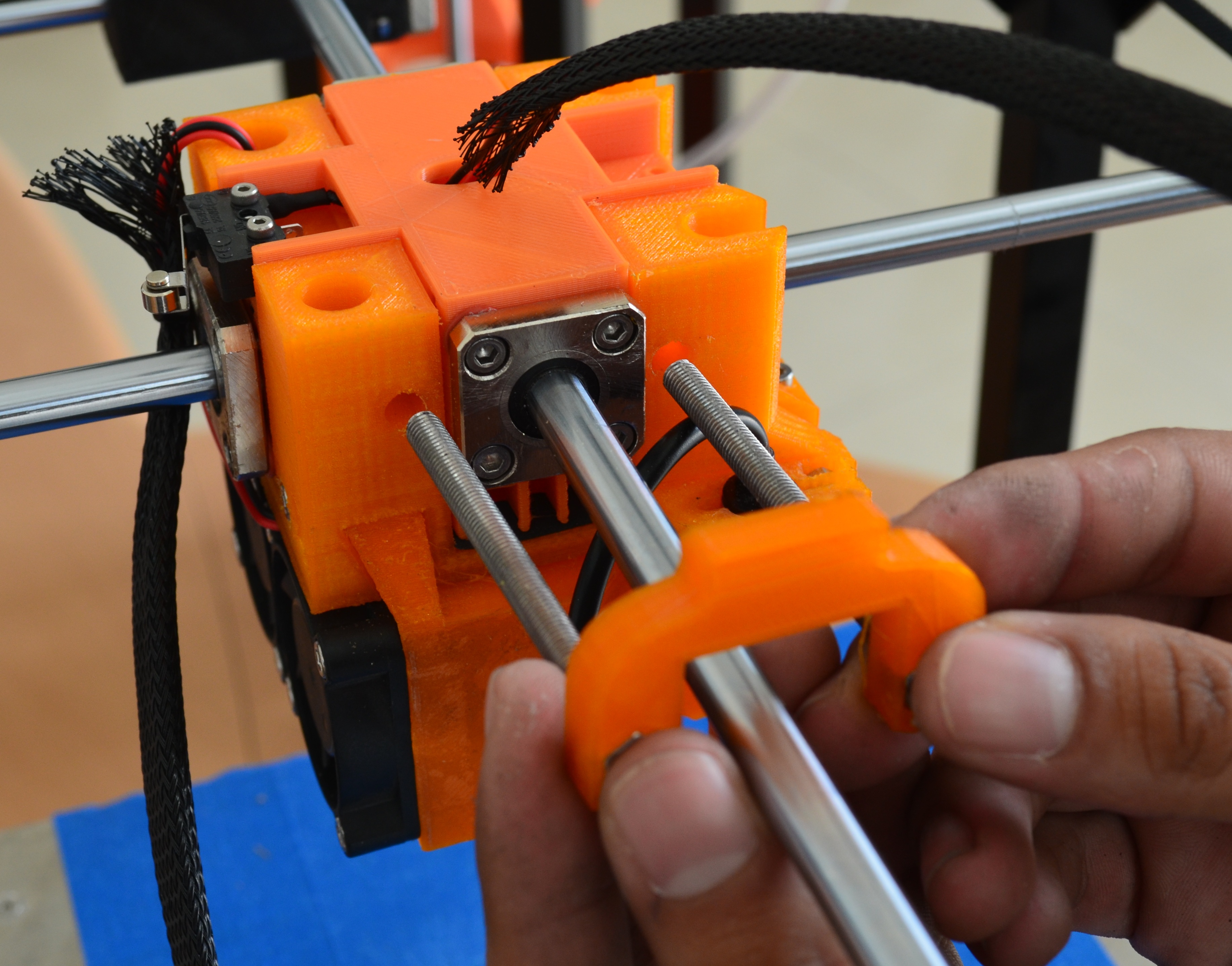
Lets unplug the Bowden tube, use Chain Nose Jaw Pliers, put the pliers under the plastic piece hole and press the blue rubber of the neumatic connector, dont close the pliers, use them only to press down the connector.
While you press the rubber of the neumatic connecyoryou have to pull u the Bowden tube to unplug it.
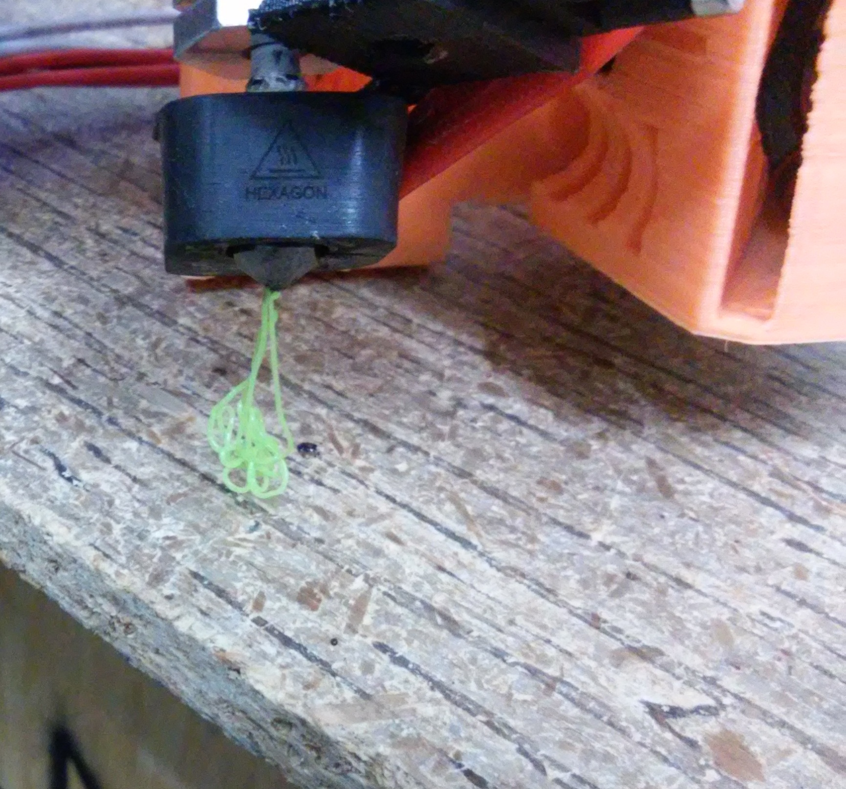
Step 3
Once the noozle is hot and the bowden is unplugged, put a piece of filament to purge the noozle manually, and check if the problem solves.
While you put the piece of filament into the noozle press down trying to get the jammed filament out, if it doesn´t come out, quickly pull up the piece of filament.
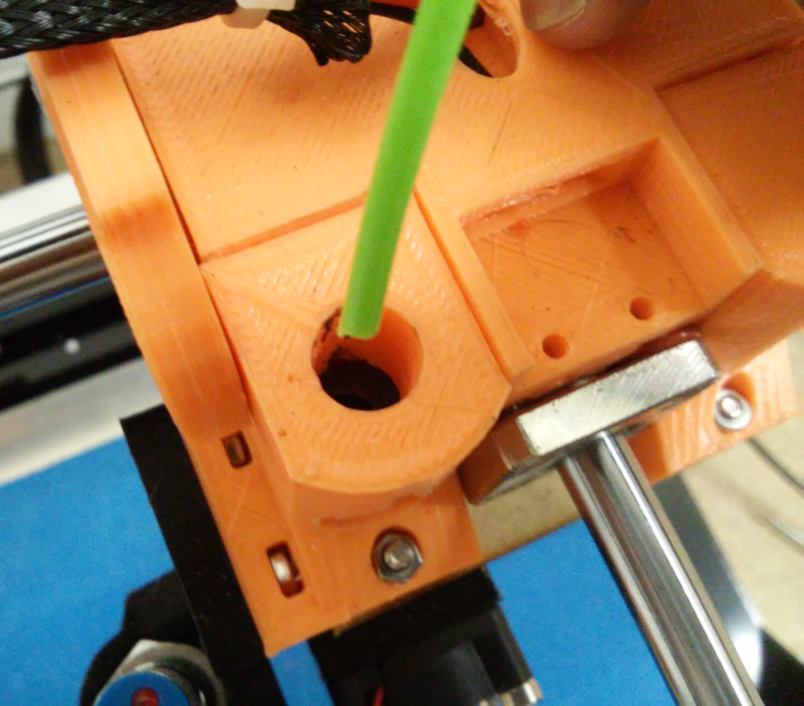
When the material is jammed in the end of the nooze it will begin to stick to the new filament. repeat this operation until no more carbonized filament comes out.
If it works and the filament comes out from the end of the noozle, you can plug the bowden tube again and print.
If the material doesn´t come out, maybe is still jammed, to clean you have t follow these steps:
Step 4
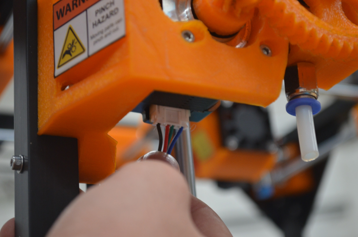
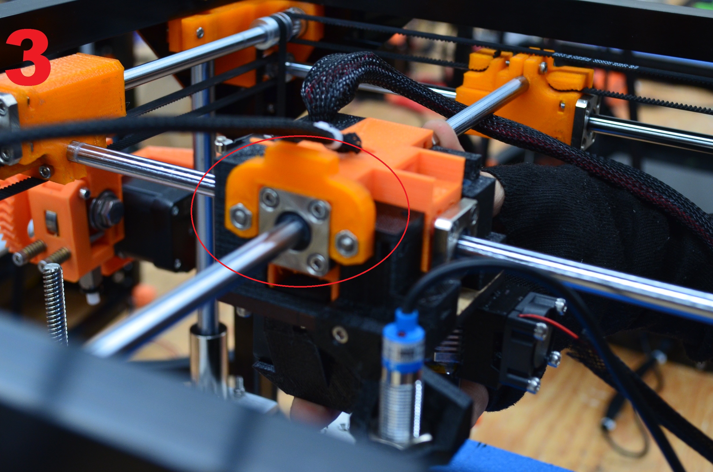
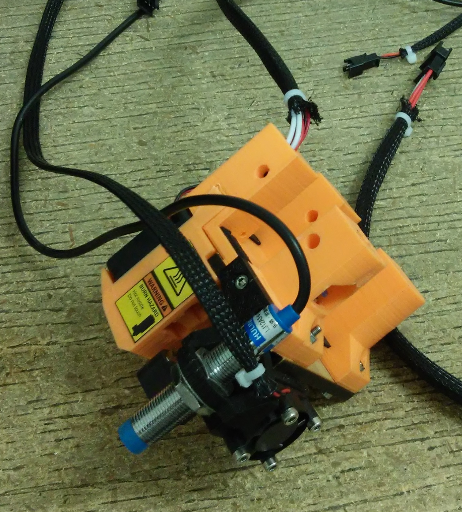
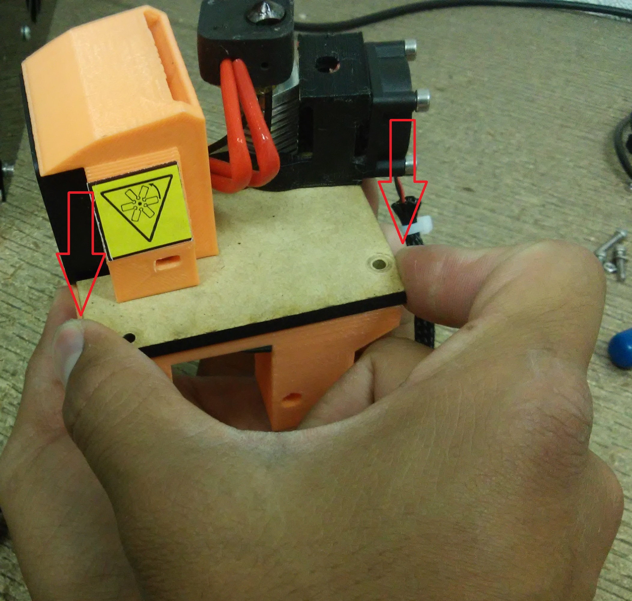
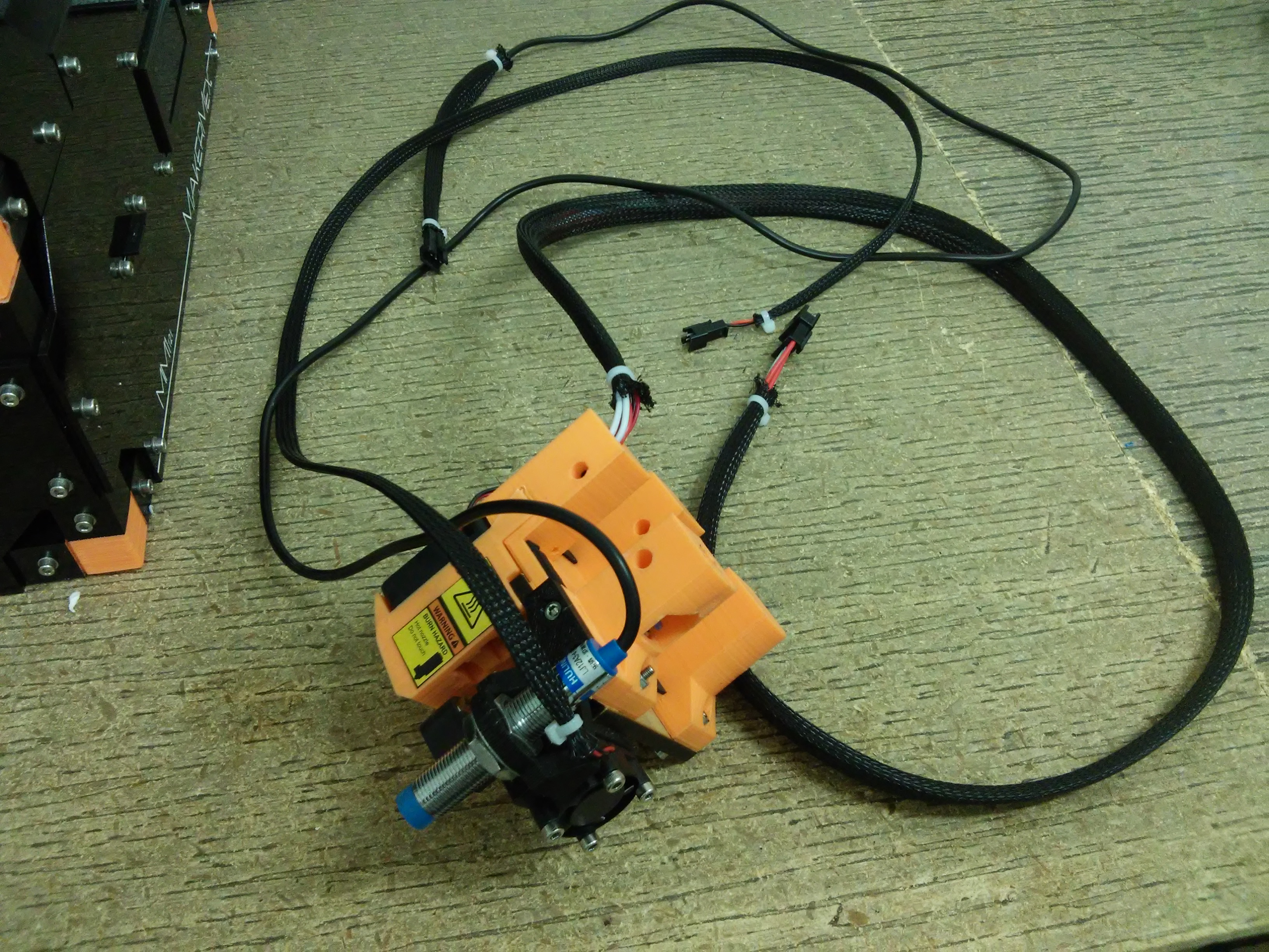
Turn off the printer, remove the module clip and unplug the wires to remove the whole module and disasemble.
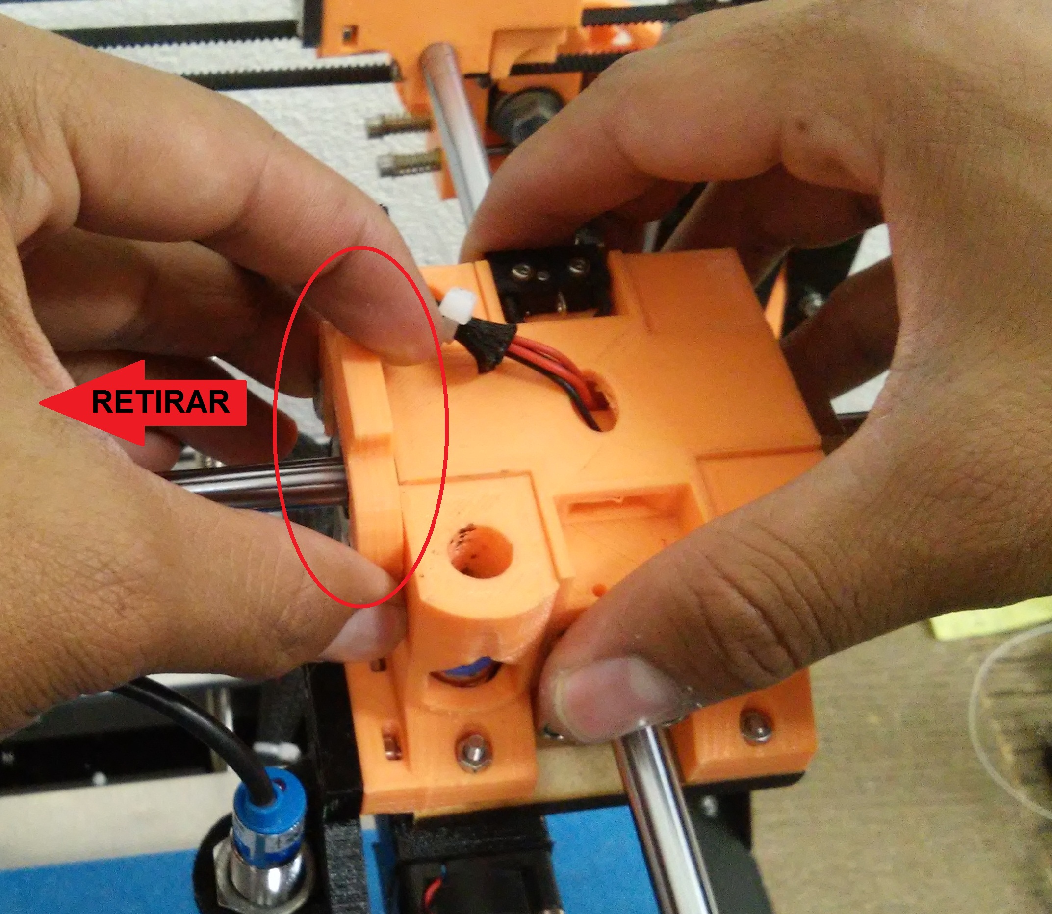
Unplug the following connectors
Only leave the double extrusion clock
Note
From the 3D printer with serial number 198 and above, dual extrusion tumbler is not necessary for the machine or any module, and is not included, this feature is now included in the controller firmware; if the serial number of your machine is lower than 198 and you want to update the firmware please contact our support team via the forum .
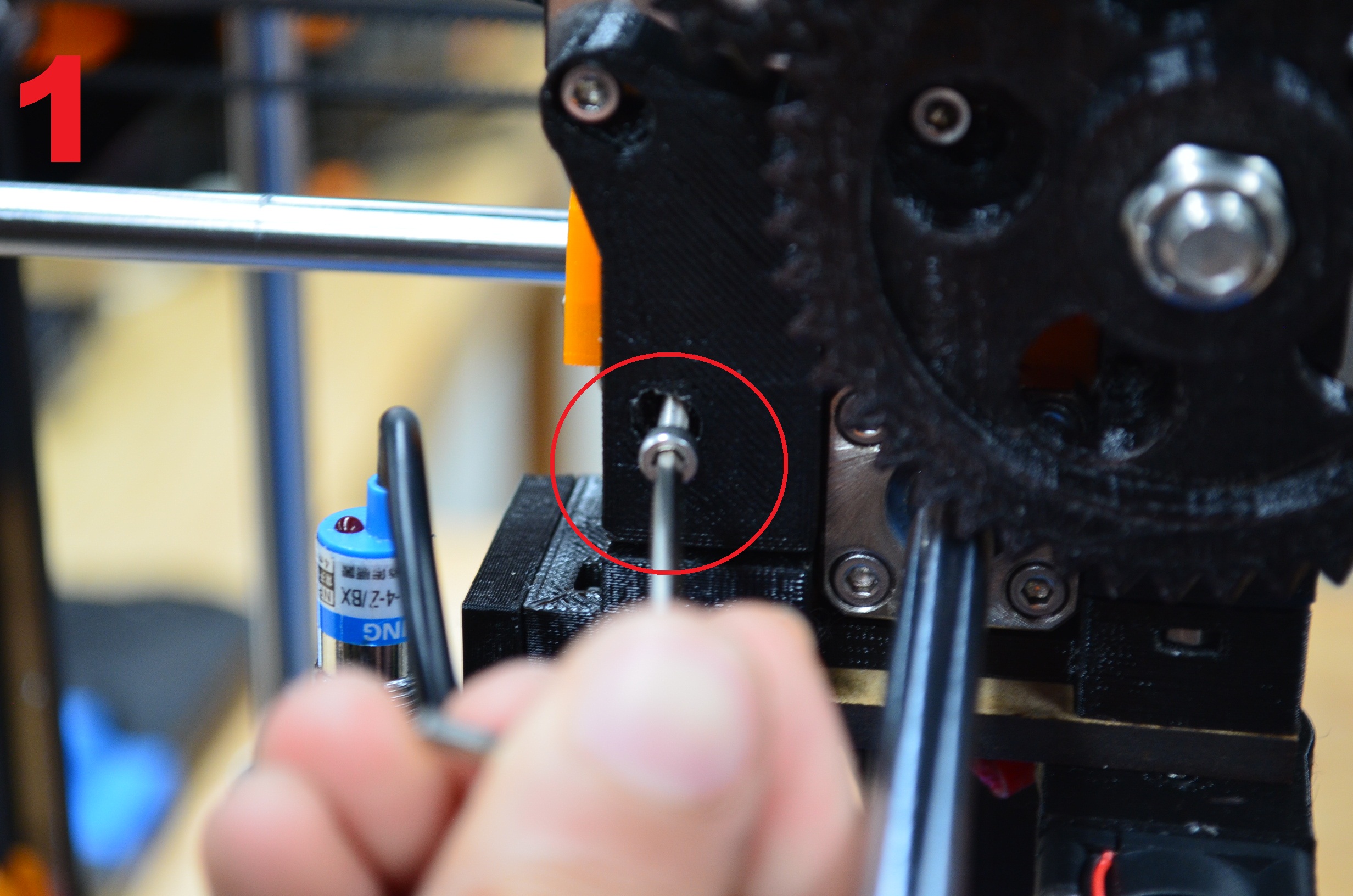
Dismount the module of the cross.
Step 5
Lets disasemble the módule, to get access to the noozle.
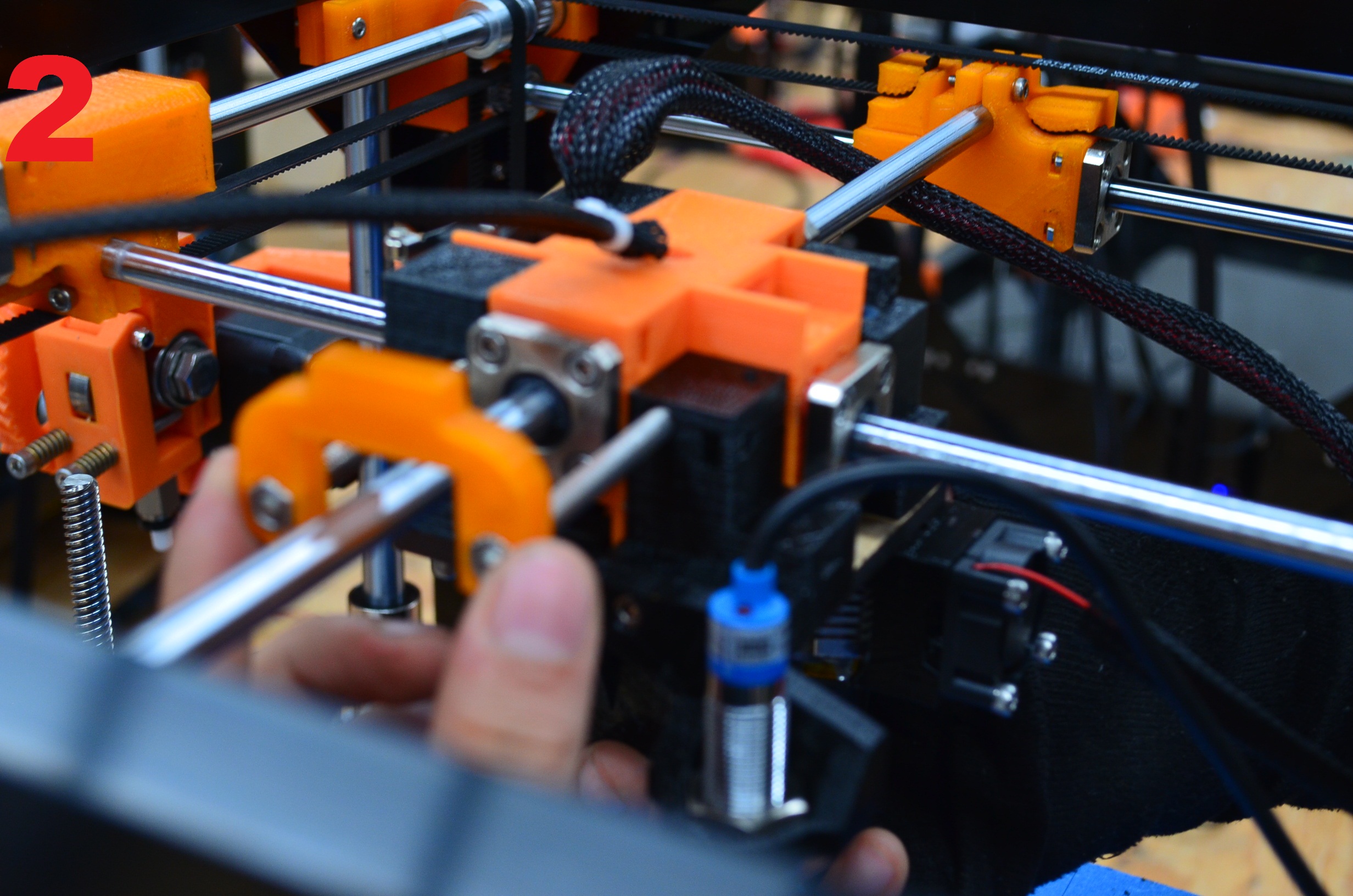
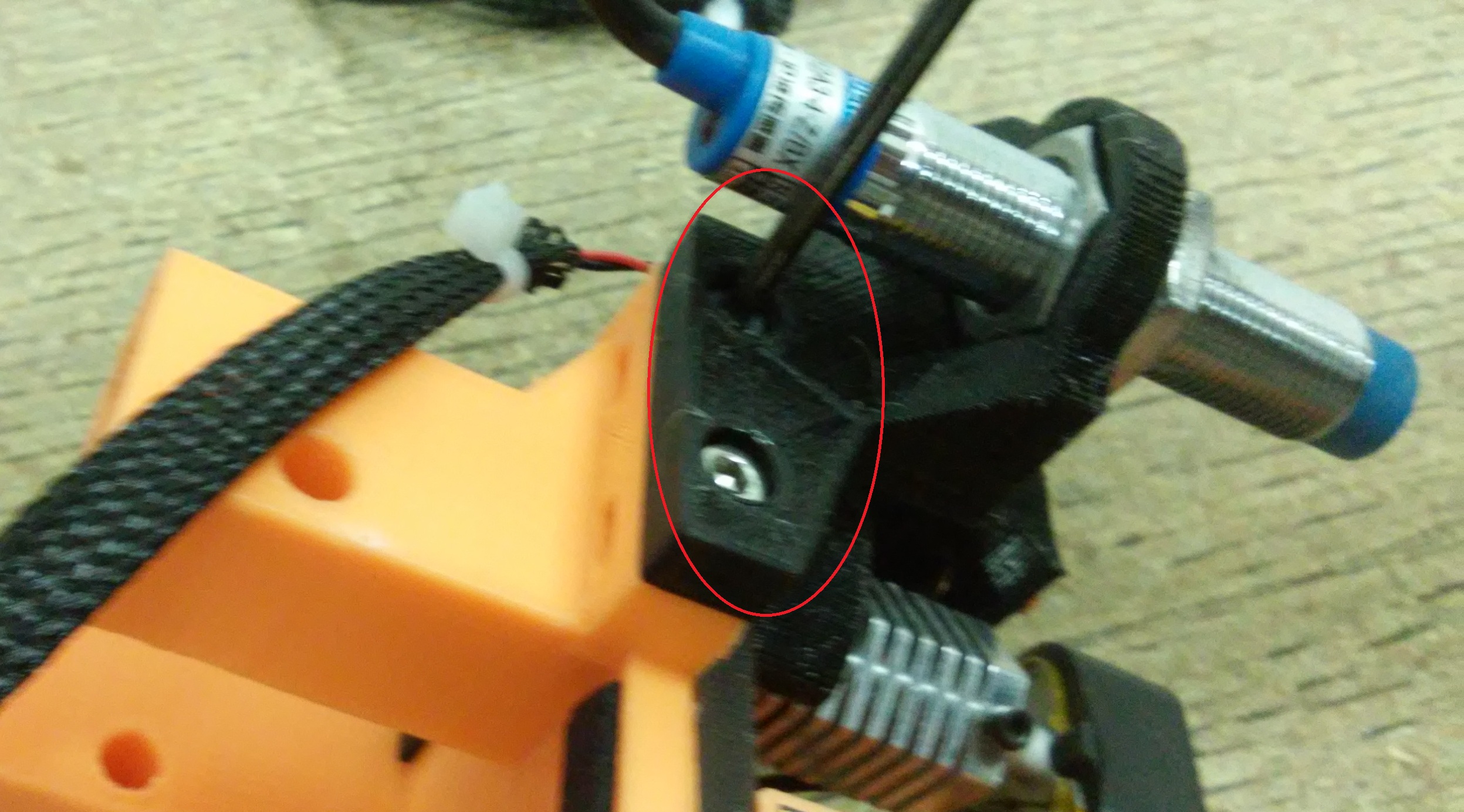
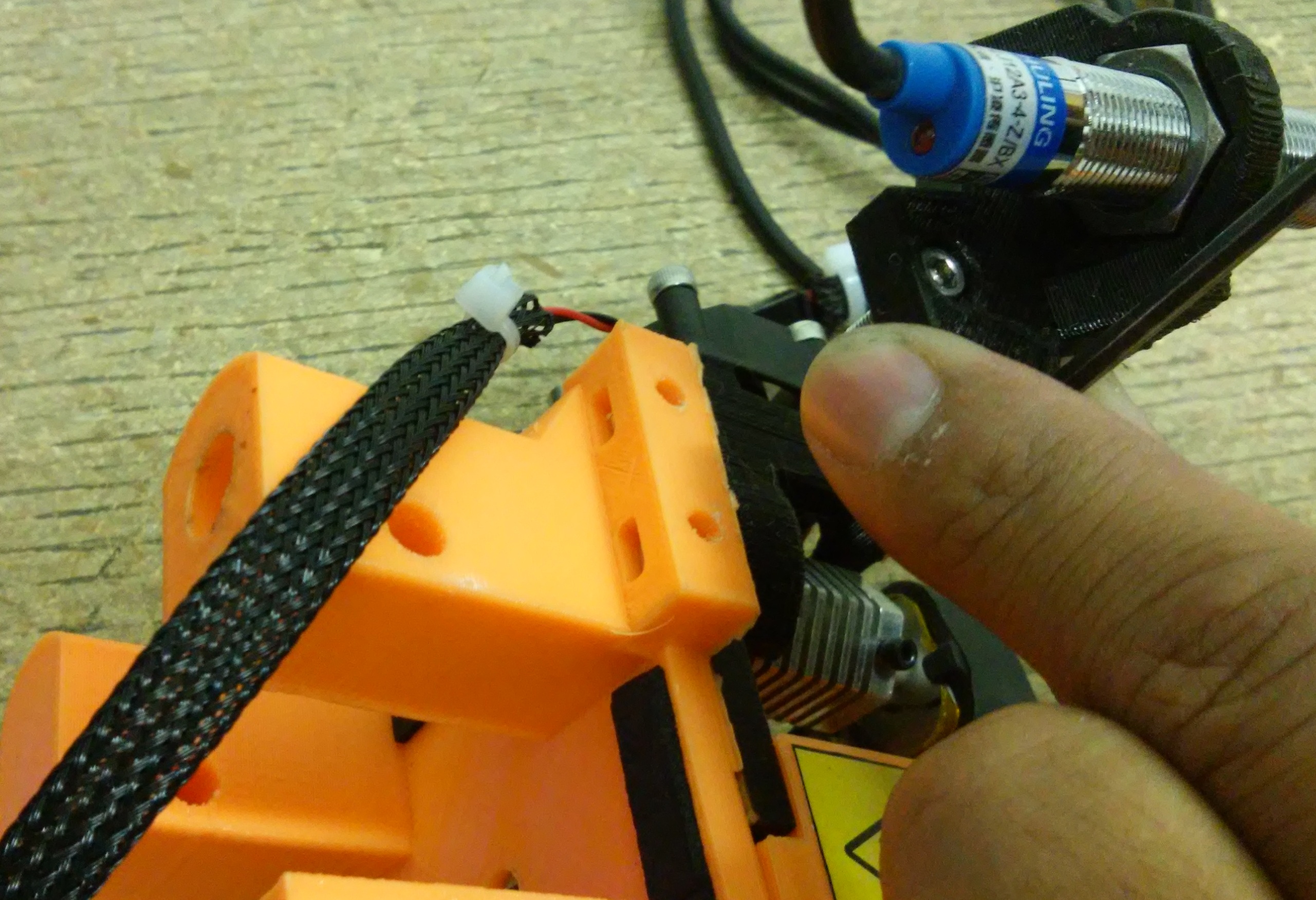
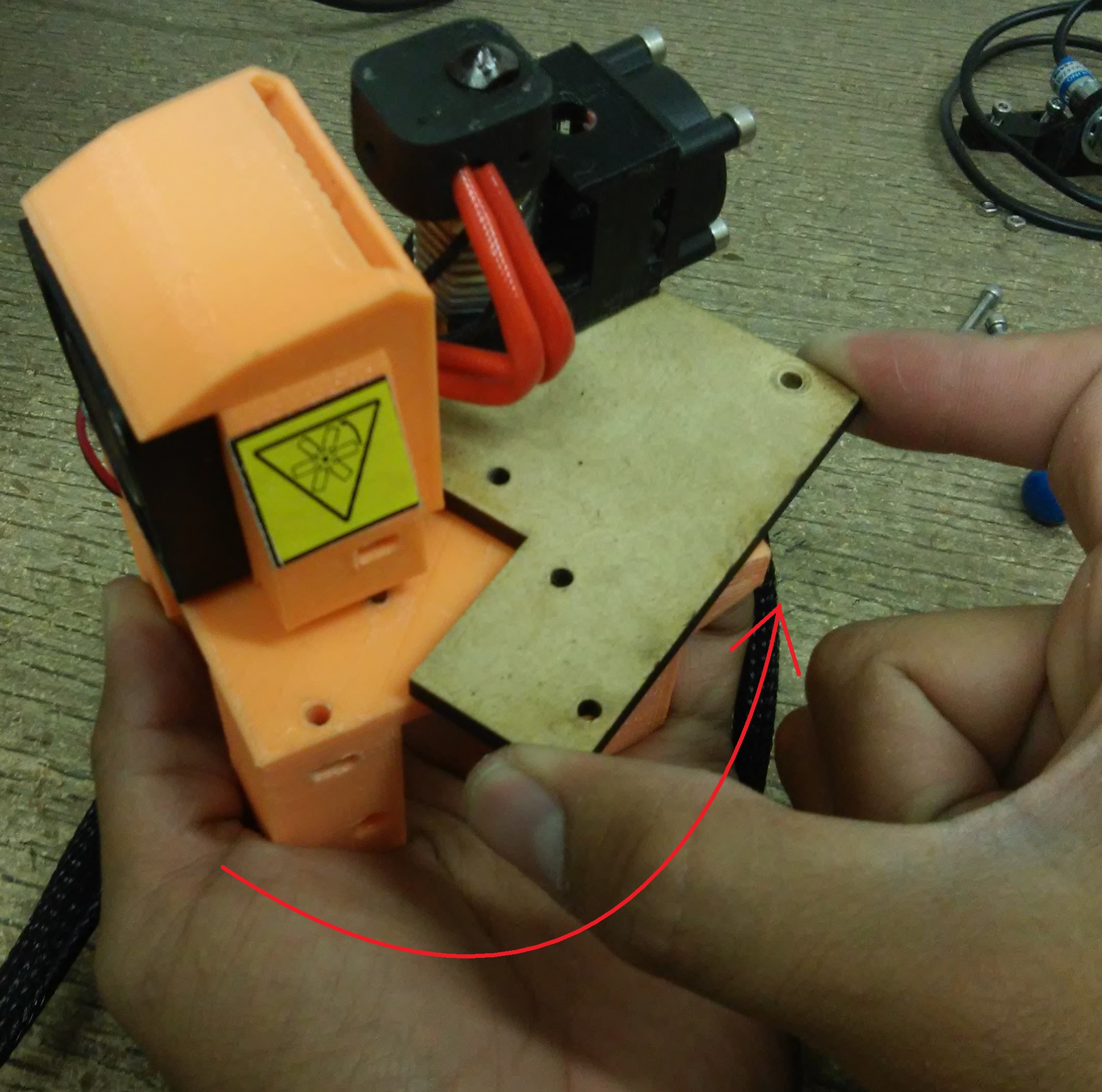
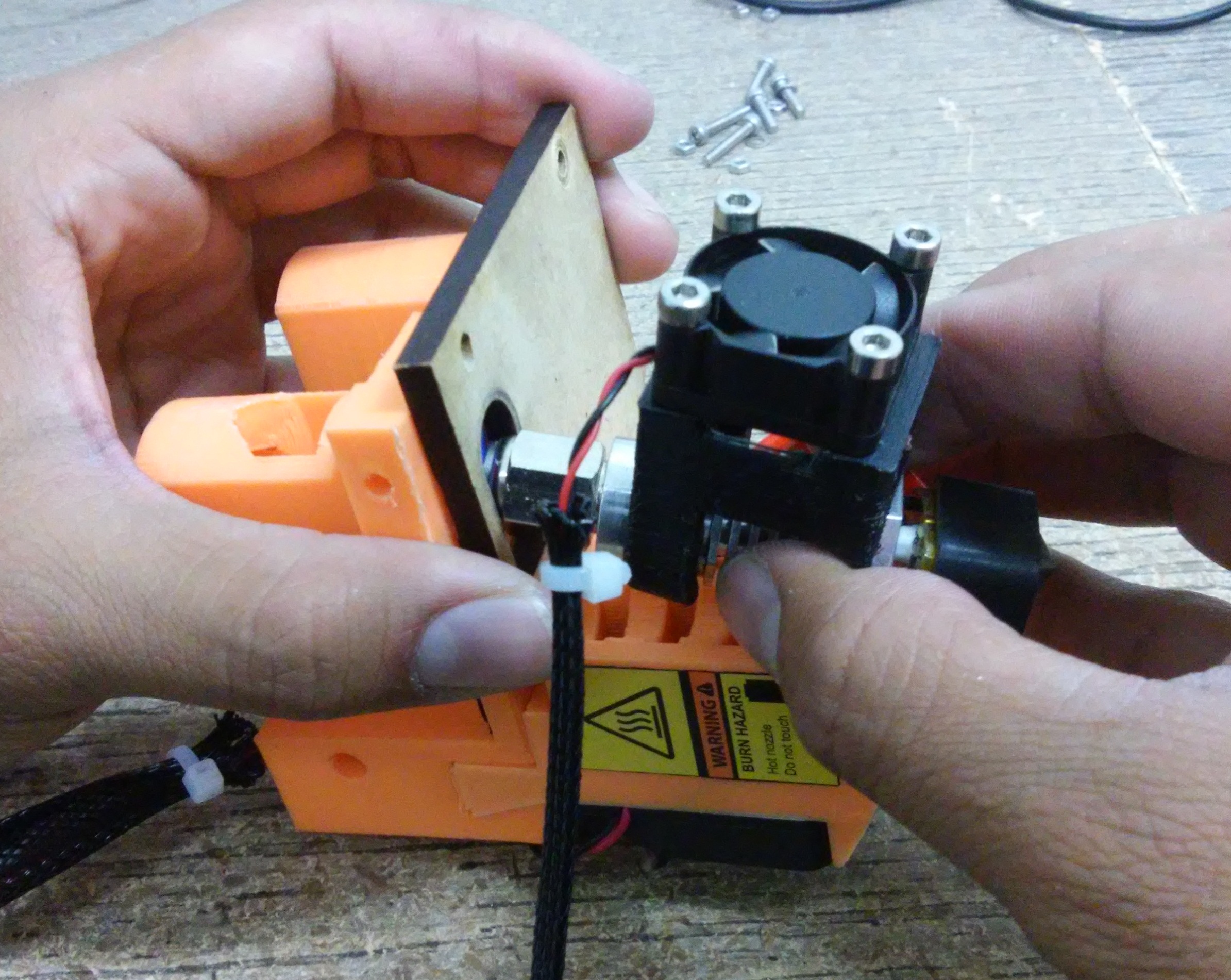
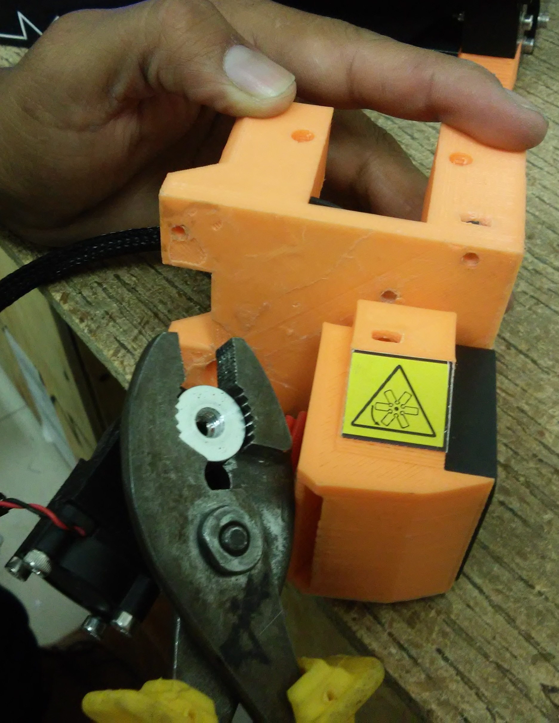
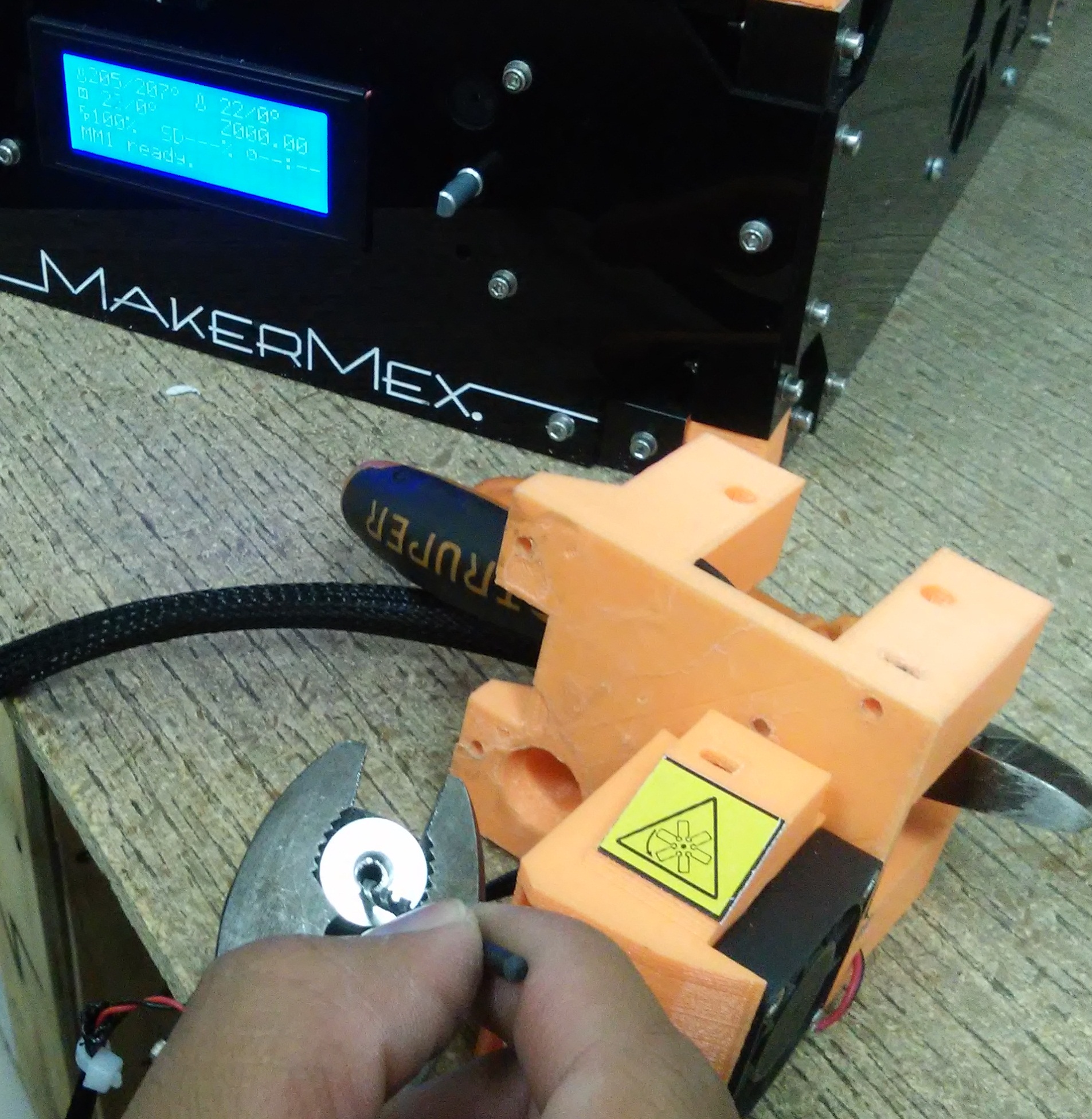
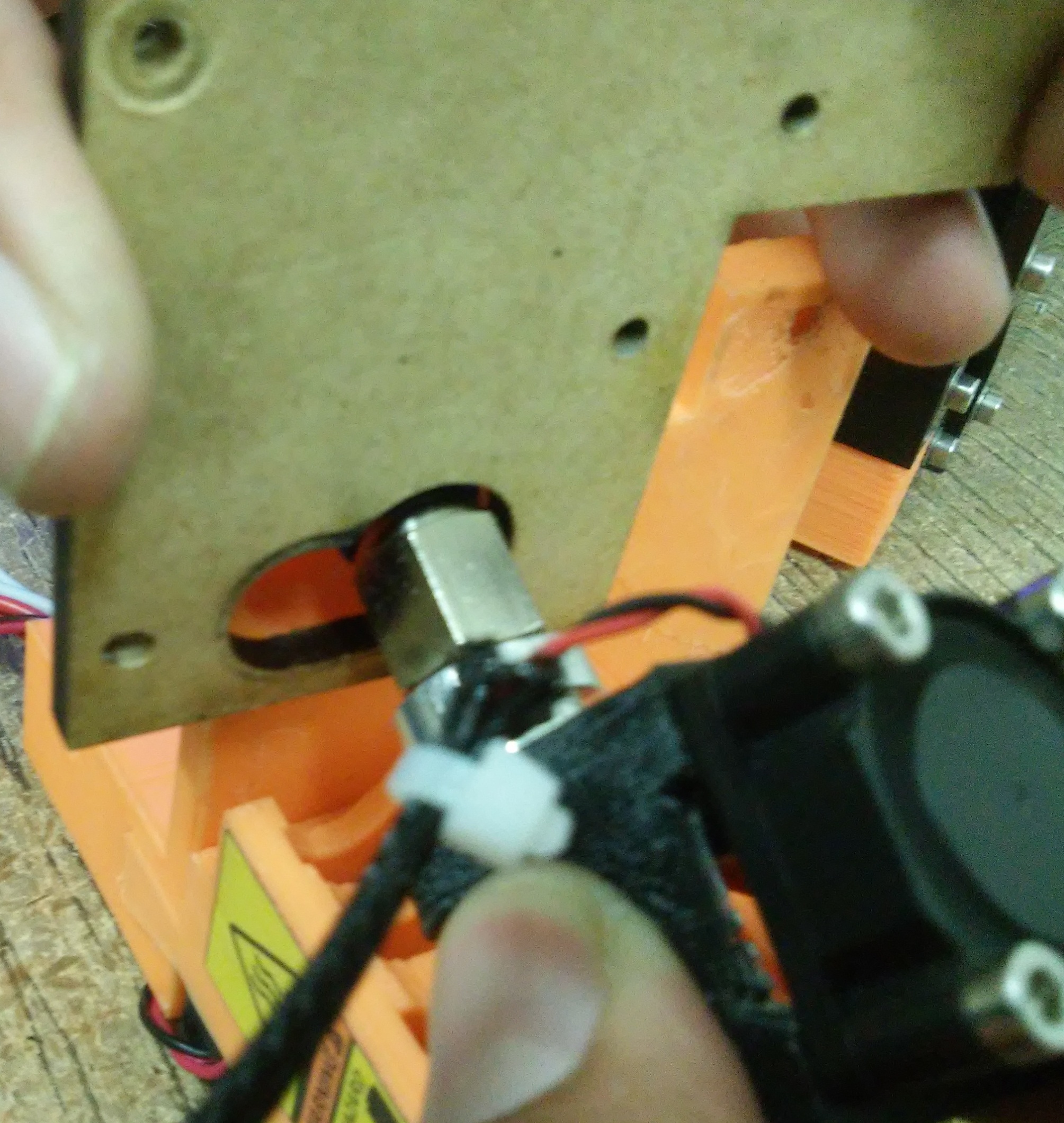
First we have to remove the screws fro the plastic piece of the inductive sensor, these screws must be removed using a 2.5mm allen wrench
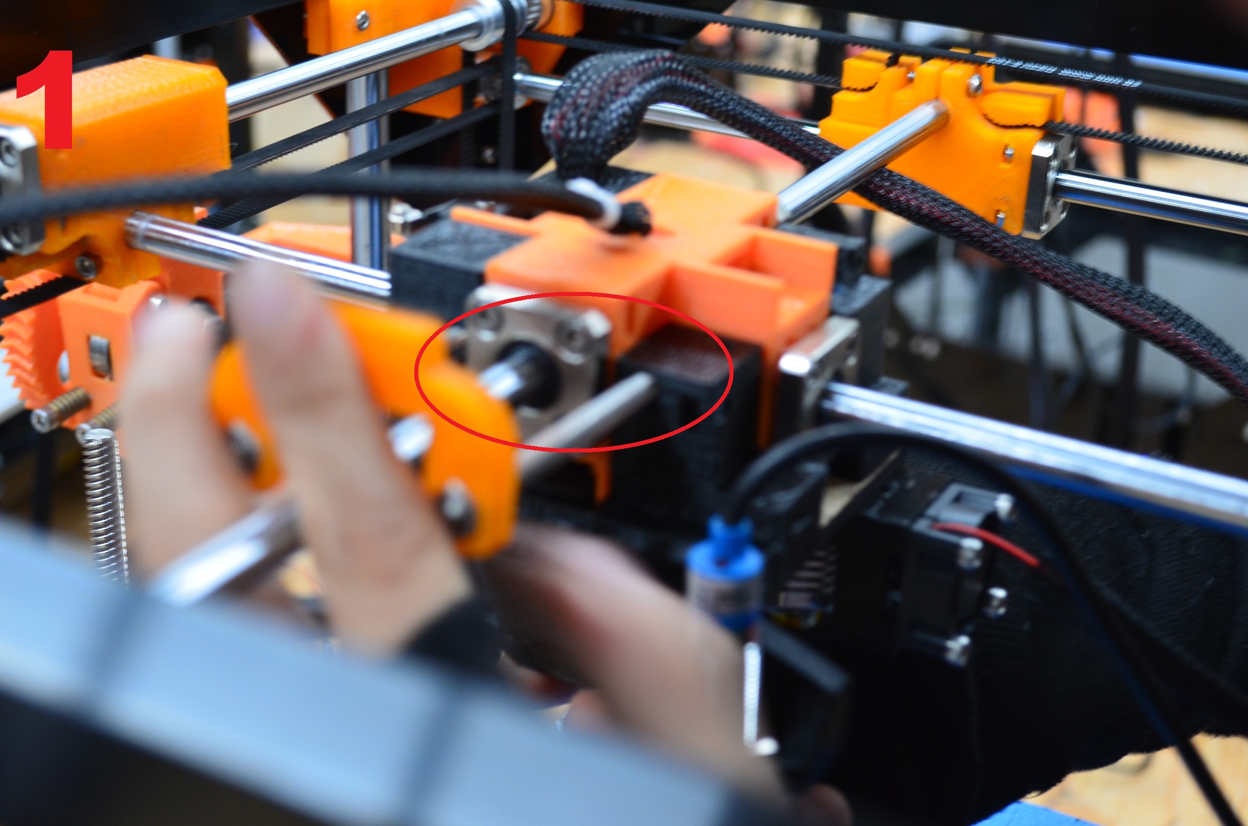
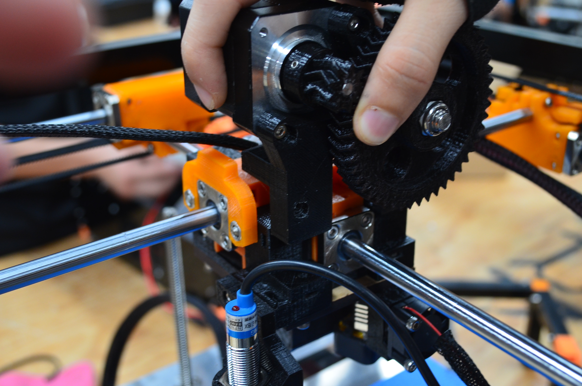
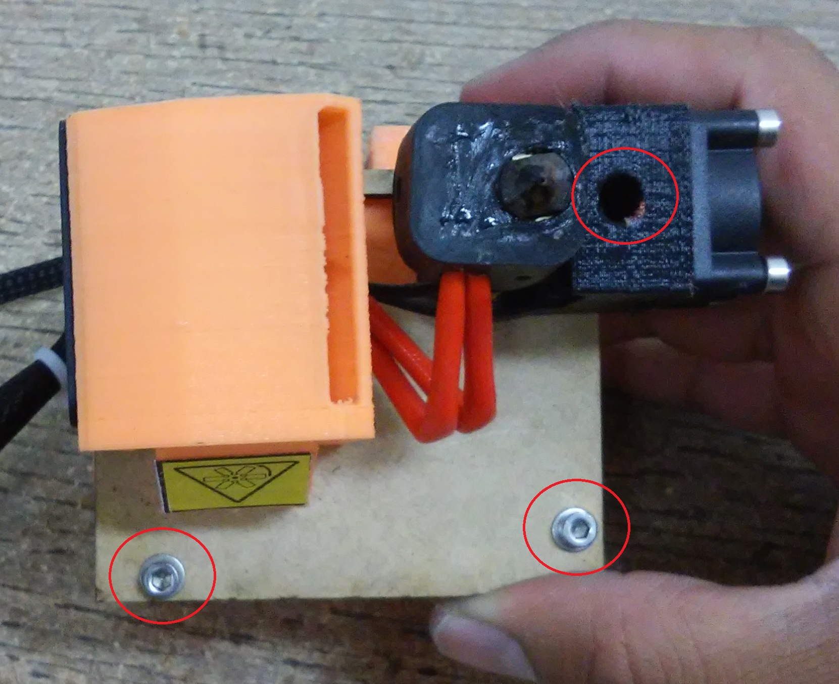
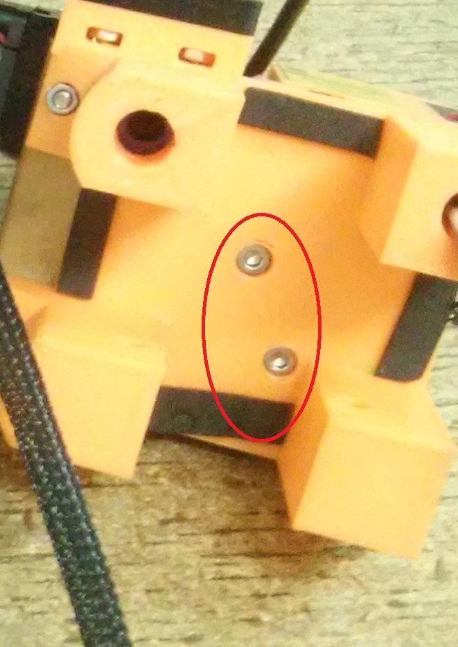
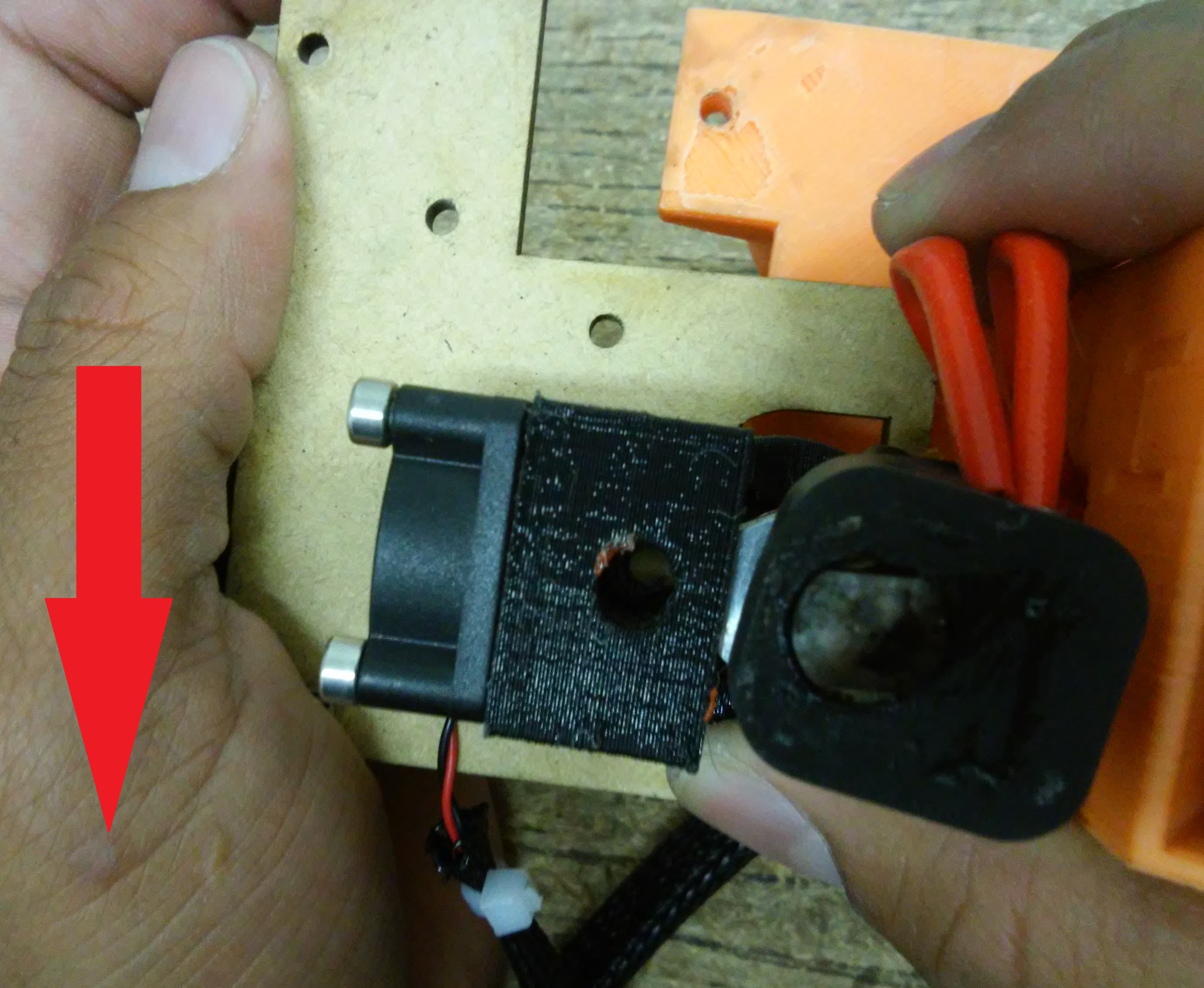
Lets remove the screws that hold te the MDF to the module, in the image are marked with red circle, there are 3 in the bottom part and 2 more in the top part. use a 2.5mm allen wrench
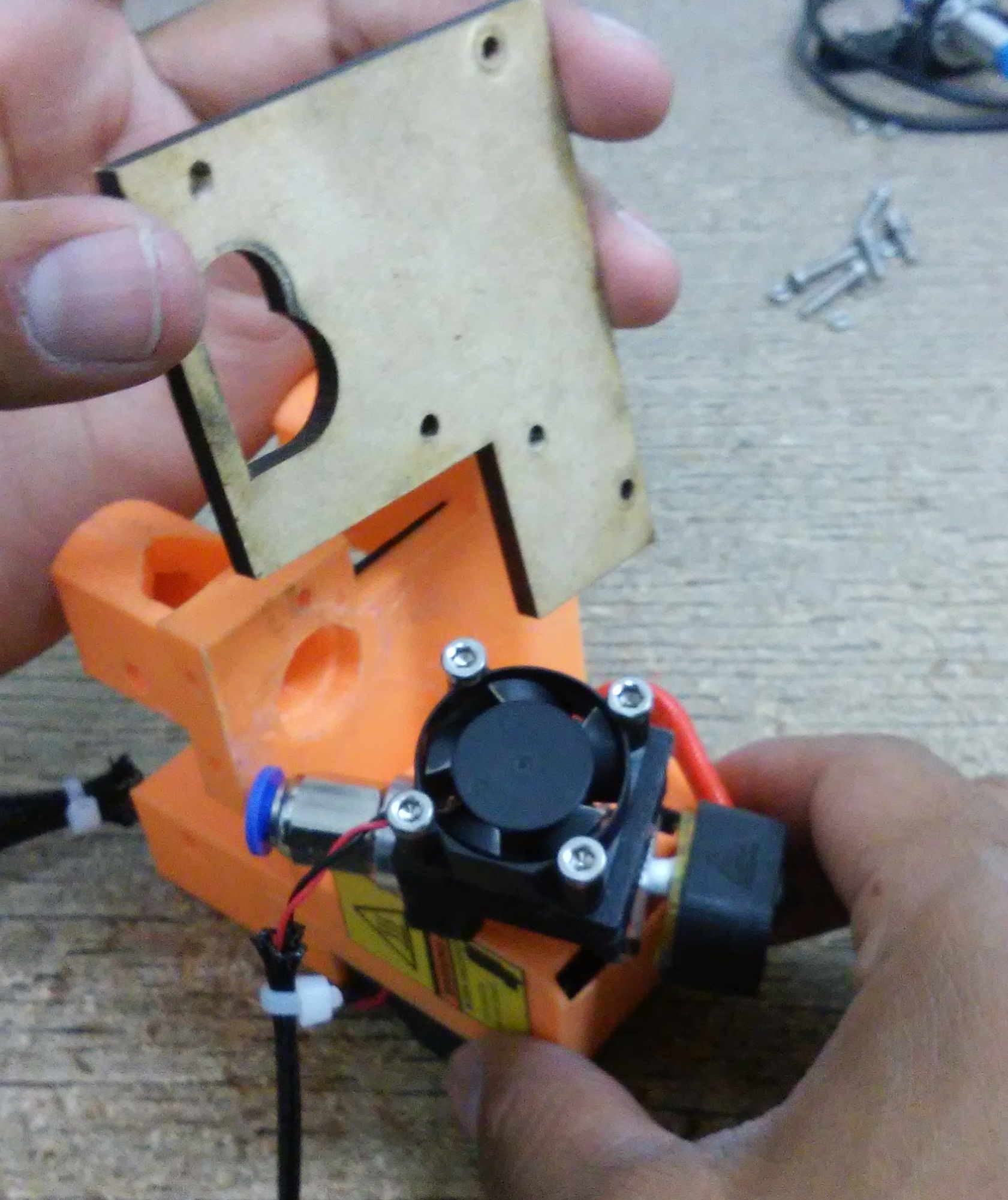
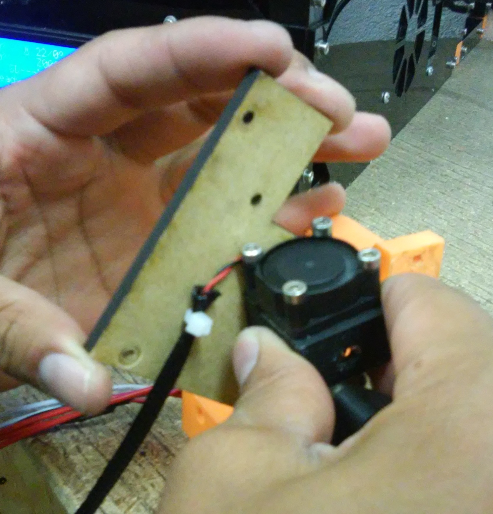
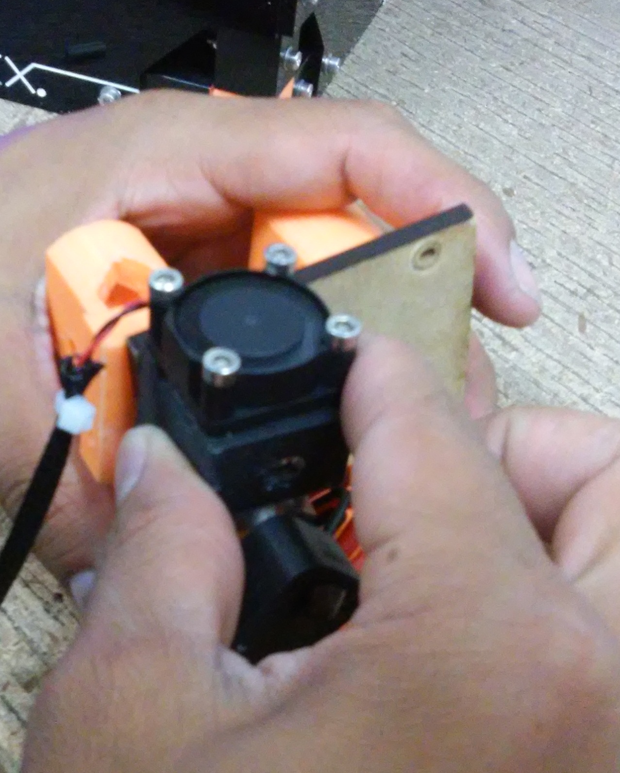
Step 6
Lets remove the MDF to release the noozle, turn the MDF outside while you hold the MDF with the tumb and index finger.
When the MDF is in the position shown in the picture push it following the row to release the nozzle and make easier to clean it up.
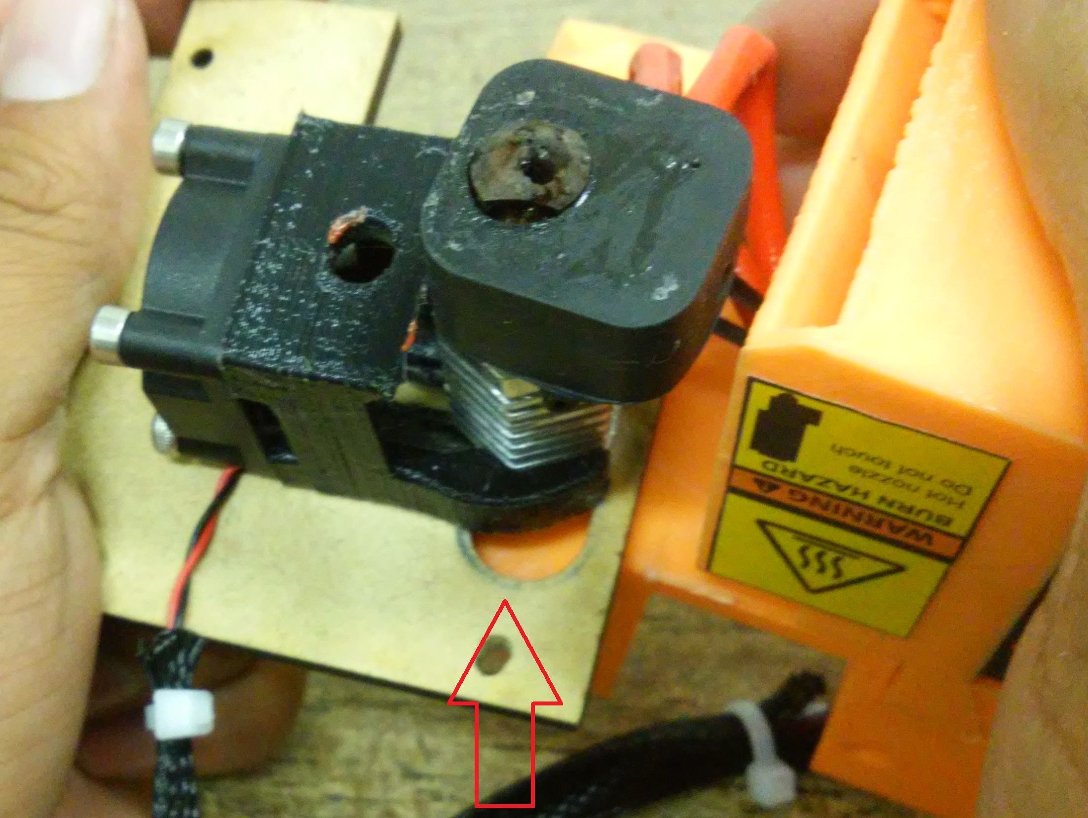
Be very careful to remove the noozle trough the biggest hole of the MDF.
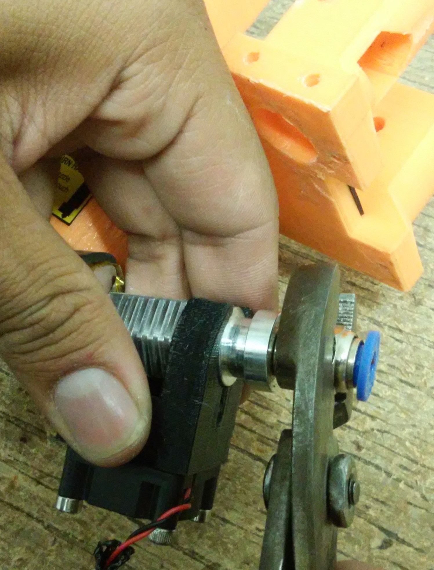
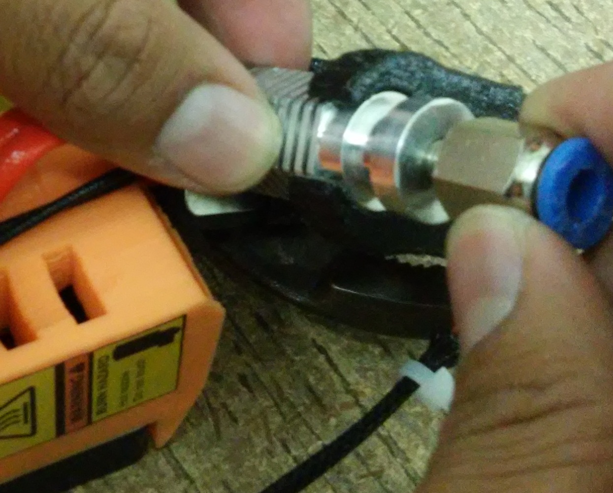
Step 7
Remove the neumatic connector of the noozle, in this step we will hold the noozle very carfuly, use slip joint pliers to hold it and then unscrew the connector.
Step 8
Lets plug the small fan to the printer and als the 6 i connector to heat up the noozle.
After we connevt gthe module, turn on the printer.
Using the LCD screen heat up the noozle to the temperature recomended for the jammed mterial, for PLA between 200°C and 210°C, if ABS the temperature is 220°C to 230°C.
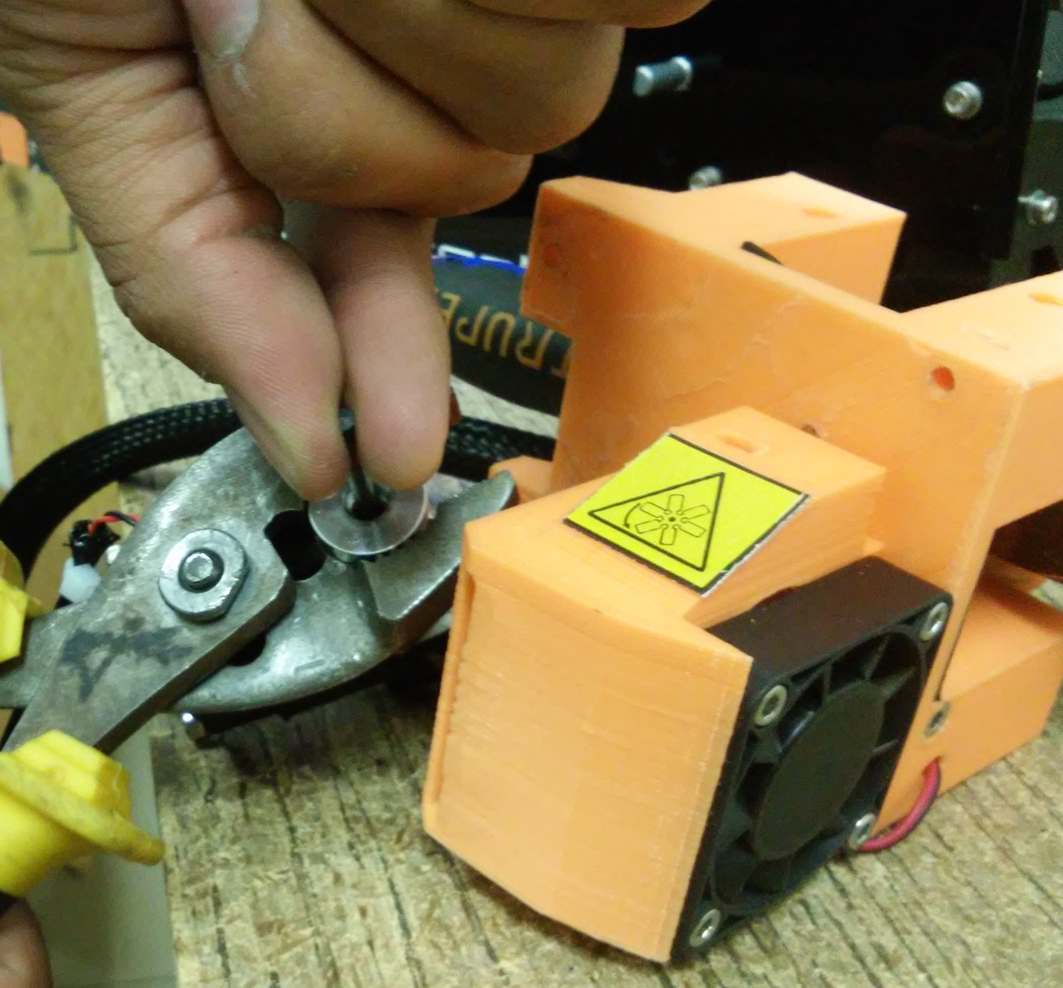
In this example is PLA, so lets use a temperature of 207°C. when is hot, hold the noozle with the pliers.
Put a 3mm drill bit into the hot noozle and turn it by hand, dont press, only twist it slowly and pull up to remove the material that sticks to the drill tip.
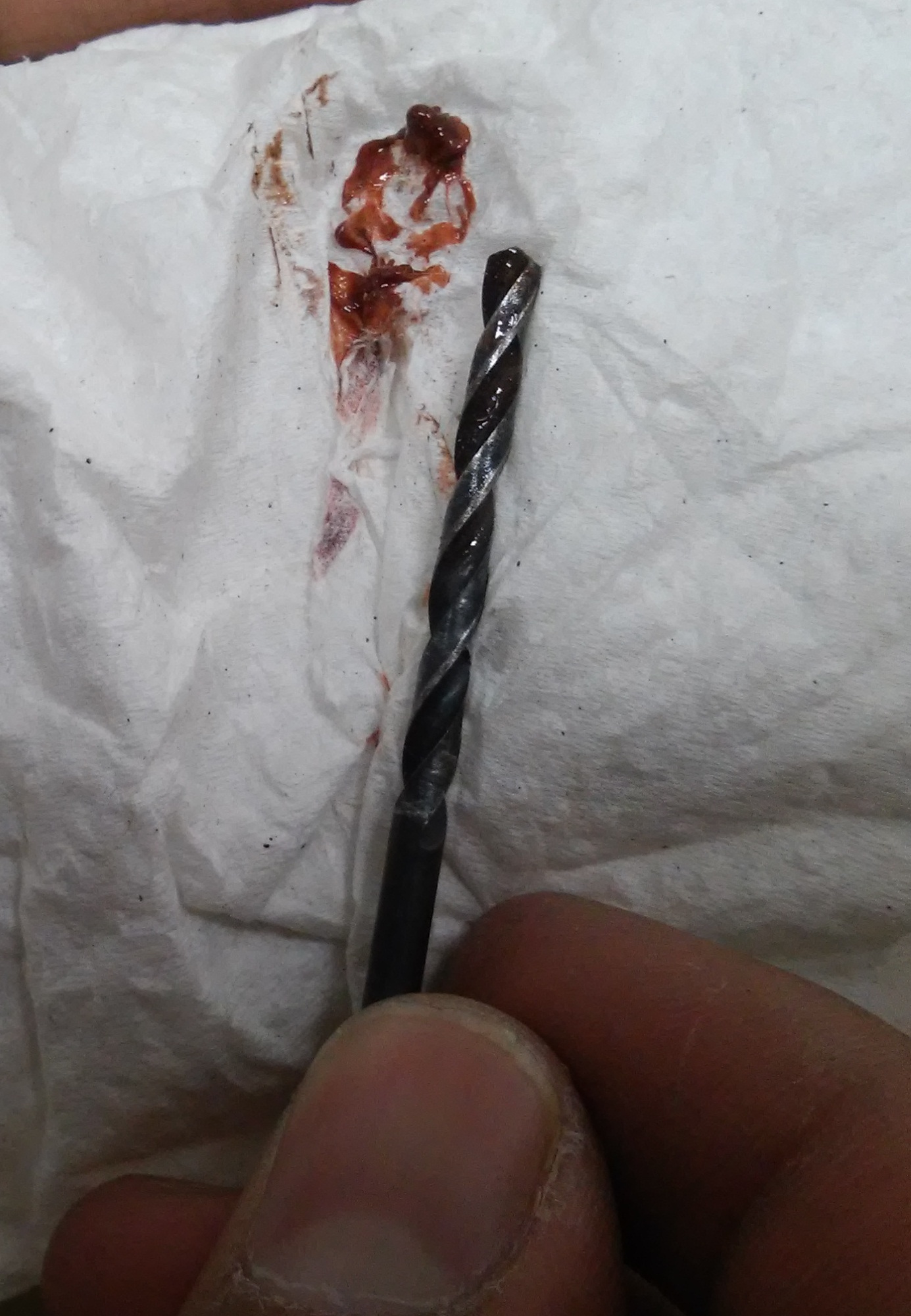
Repeat the steps until you remove all the remanent of filament from the noozle.
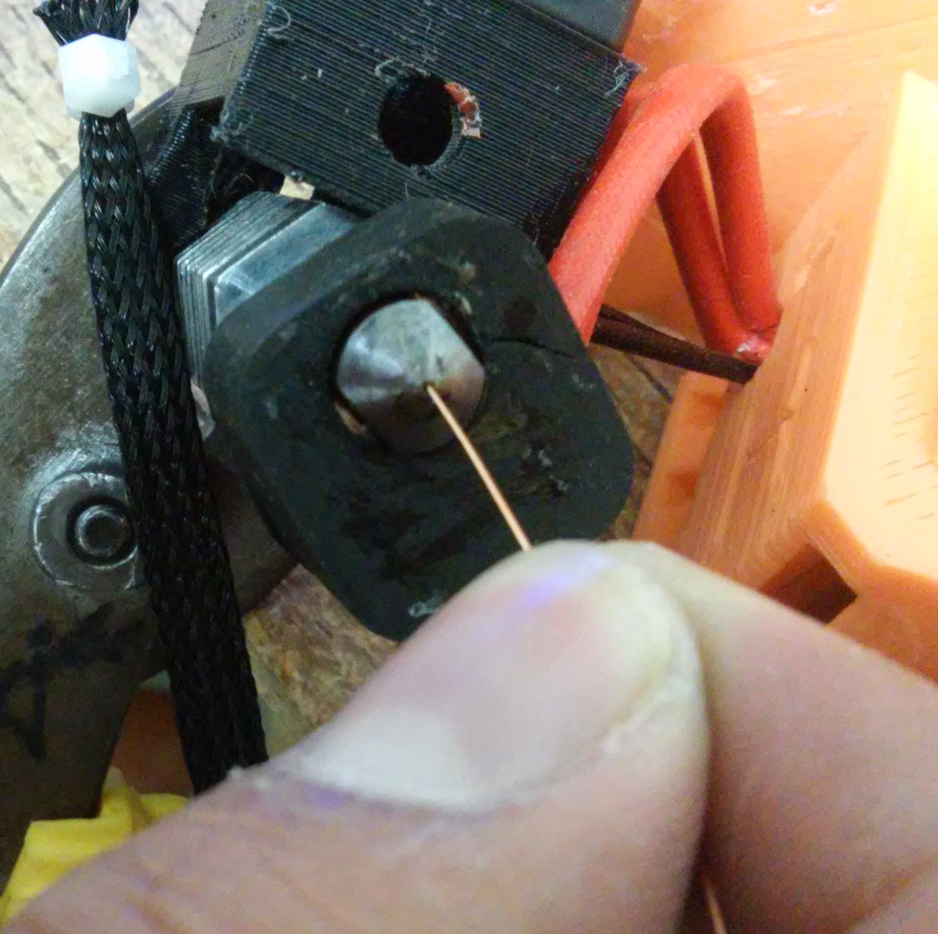
Now we clean the end of the noozle with a thead of a 12 or 14 cupper wire.
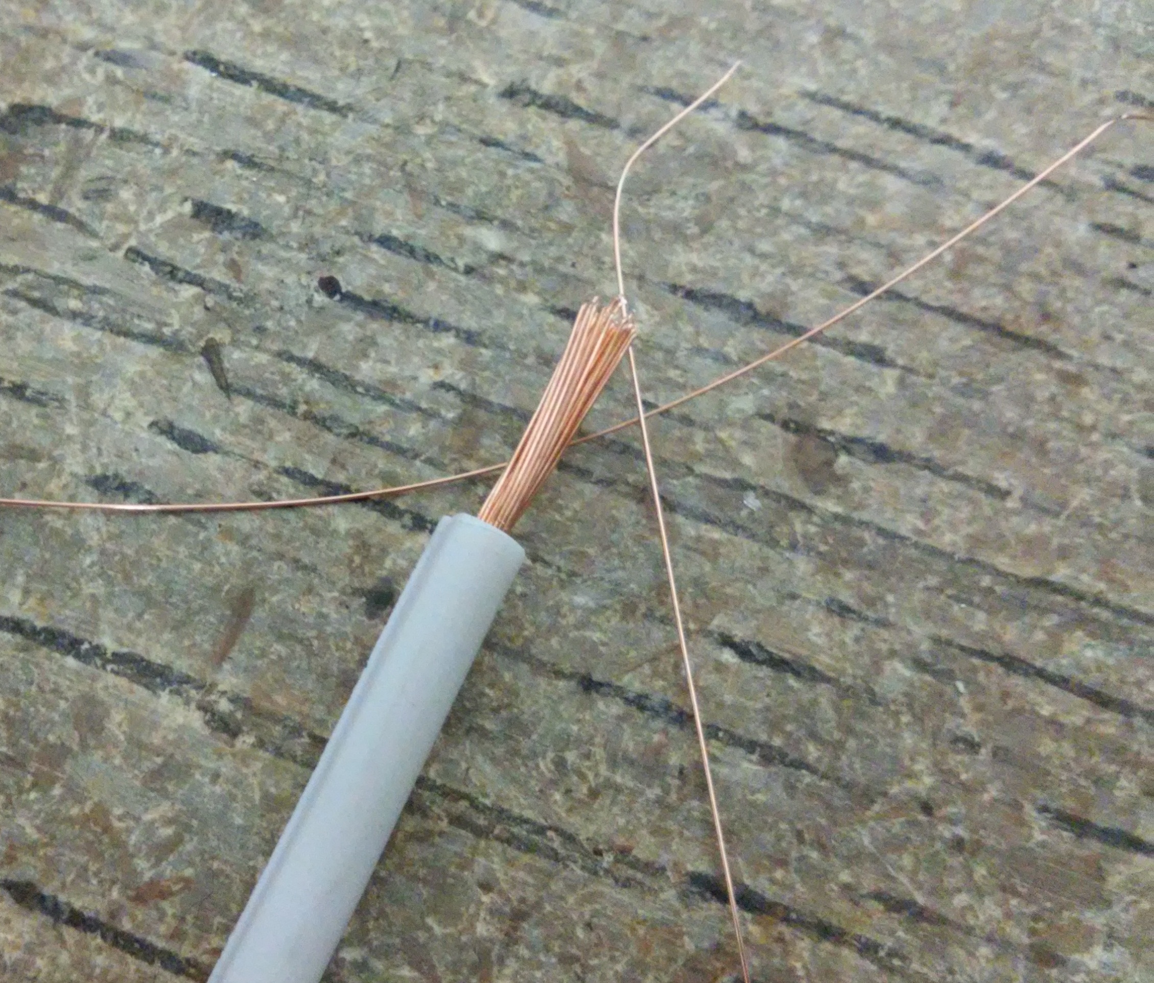
Again, repeat that operation as many times as you need to clean the noozle.
Step 9
After cleaning and removing the remanents with the drill bit and the cupper thread, we will purge with a piece of filment, as we did in the step 3, put the piece of filament into the noozle, press down and pull up with a fast movement. cut the part of the filament piece that has remanents sticked to it. Do this as many times as needed, until there are not black dots of carbonized filament in the piece.
After the purge we can observe that the noozle is clean and mterial comes out freely.
Step 10
Once we cleaned the noozle, turn down the printer, get the piece of filament out and after a few seconds turn down the printer again. This will cooldown the noozle, when you look in the LCD screen that the noozle reached room temperature assemble the module as originally.
Screw the neumatic connector
Put the MDF in the noozle, ensure that the smallest hole remains holding the noozle
put the noozle into the plastic piece hole and turn the MDF to their original position.
Lastly, put the 5 screws to hold the MDF to the plastic piece. put the inductive sensor ans then the mdule will be ready. to use
Automatic bed calibration
Have you had calibration problems with your printing plate?
One of the must frustrating problems when you have a 3D printer is the bed leveling, this is a matter of patens to get the correct compression of all the springs to get it well calibrated.
The best solution to these problem is the autoleveling of the printer, to get this you have to modify the Gcode of the model to print.
The first step is to know your printingcmachine and its working space, because the auto leveling works with some points predefined in the firmware.
Marlin Firmware
Marlin firmware is an informatic program that controls the 3D printer electronic board at the lowest level, there are many variations of Marlin Firmware as soon as there are many models of 3D printers on the market, you hve to be sure you are using the correct Marlin Version for your 3D printer.
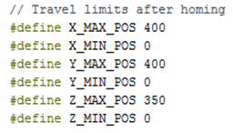
Every Marlin Firmware is divided by 50 sections or files, the fle that we will modify is configuration is configuration.h This file is divided in 5 parts (Thermal Settings, Thermal Runaway Protection, Mechanical Settings, Bed Auto Leveling, Additional Features), we will modify the Bed Auto Leveling section, but first you have to define the working area dimentions, these are defined in the Mechanical Settings section
In this example the printer has a working area of 400x400x350 milímeters.
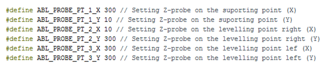
Once you define the working area you have t define the leveling points
By default Marlin have defined 3 leveling points in the Bed Autoleveling section of the configuration.h file, you can modify the X and Y coordinates as needed. in this example we used the follwing coordinates for the 3 points:
Note
The coordinates of the points must be inside the limits of the working are to avoid accidents.
Last step is to configure the auto leveling speed, a moderated speed is 1500 mm/min. this is defined under the coordinates config.

Now just load the modified Marlin to the 3D printer.
After you have configured te Marlin you have to configure the GCode, we use the free software CURA.
Configuration of Cura software

You have to modify the configuration of Cura software for the auto leveling feature (The software to converts a 3D model to Gcode).
1.-Open Cura, select the printer you want to use. To select the printer go to the tools menu and go to the “Machine” tab. If you dont have added your printer press “Add new machine” and configure it.
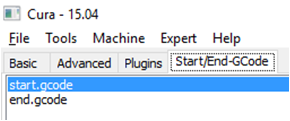
2.- now you have to select the model to print and set the printing parameters (“Basic” and “Advanced” tab). Then go t the “Start/End GCode” tab and select “start.gcode”.
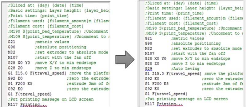
3.- In the left of the screen you have the first part of the G Code add a new line in the code between the line that says “G28 Z0” and the line thaat says “G1 Z15.0 F” the new line must say “G29”.
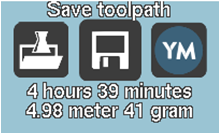
4.-Now simply save the GCode in the printer pressing the “Save Toolpath” button, now put the SD card into the printer and you will have the autolevel ready.